Store the missing spare wheel and jack under the cargo area of your Toyota Corolla Cross Hybrid (CCH).
Read more about the mount and Toyota Corolla Cross Hybrid Spare Tires
The Toyota Corolla Cross Hybrid Spare Tire Mount can get purchased from the Store
Assembly Instructions
The instructions and/or kit are provided “as is” with no warranty and no liability.
⚠️ You are responsible for all modifications to your vehicle and observing proper safety precautions. Failure to properly do so may lead to vehicle and bodily damage. You must consult the vehicle manufacturer or authorized dealer for accurate guidance, procedures, and warranty information.
⚡ Risk of electric shock is present. Familiarize yourself with and follow proper safety precautions when performing work on electrical systems.
Toyota HV emergency response quick reference guide for specific vehicles can be viewed on Toyota TIS here.
Toyota Emergency Response Guide PDF viewable here
Kit Parts
- Spare Tire Mount
- Part 1
- Part 2
- Part 3 - Hub Surface Depth
- Part 3 - low profile*
- 1x M10x40mm socket bolt
- 1x M10x25mm socket bolt
- 2x M10 washer
- 2x M10 flanged nut
- Universal Tire Hold Down
- 1x Tire Hold Down Handle
- 1x Tire Hold Down Ring
- 1x M8 cap bolt
- 1x M8 nut*
*optional
Tools Needed
- 8 mm hex driver
- Plier/Adjustable Wrench
- Insulated gloves
- Flat insulated screw driver
Compatibility
Toyota Corolla Cross Hybrid AWD (1st gen, 2023+)
Contents
Preparation
-
Park the vehicle on a level and dry surface. Ensure the vehicle is completely turned OFF and nonenergize for at least 10 minutes.
-
Open the rear cargo hatch.
-
Remove the cargo floor liner by lifting up on the rear edge and lifting it out of the vehicle.
-
Remove the foam block with Tire Puncture Kit from the vehicles.
Power Connector
Wear insulated gloves, shoes, and clothing. Ensure the work environment is completely dry before continuing.
-
Pry the black plastic retainer tab outwards from the white plastic lever with an insulated flat tool.
-
Disconnect the orange power cable connector in the center of the cargo space by lifting the white plastic lever upwards.
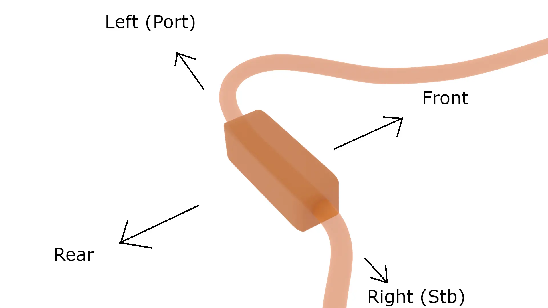
The diagram of the spare wheel well is oriented like above.
Avoid excessive force when handling the mount parts If pieces fit too tightly, lightly tap a corner of the part with your fist or soft mallet.
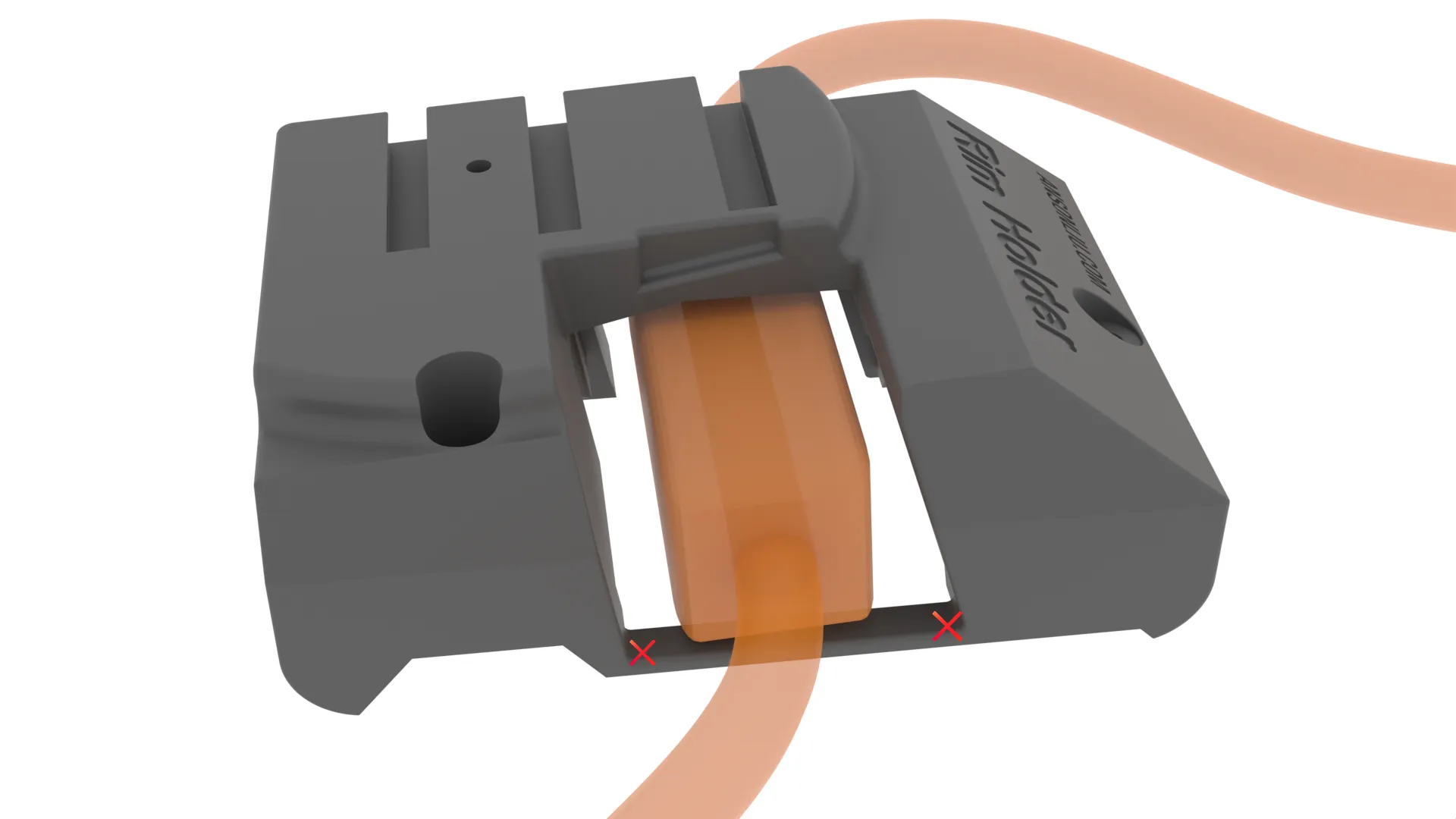
Cable Disconnect-free installation (Unsupported)
If you do not want to disconnect the power connector to attach the tire mount, the lower member of Part 1 can be removed with a fine-toothed saw and sanded smooth at the marked spots below to fit around the cable lever. The tire mount will be weaker and less rigid with this method.
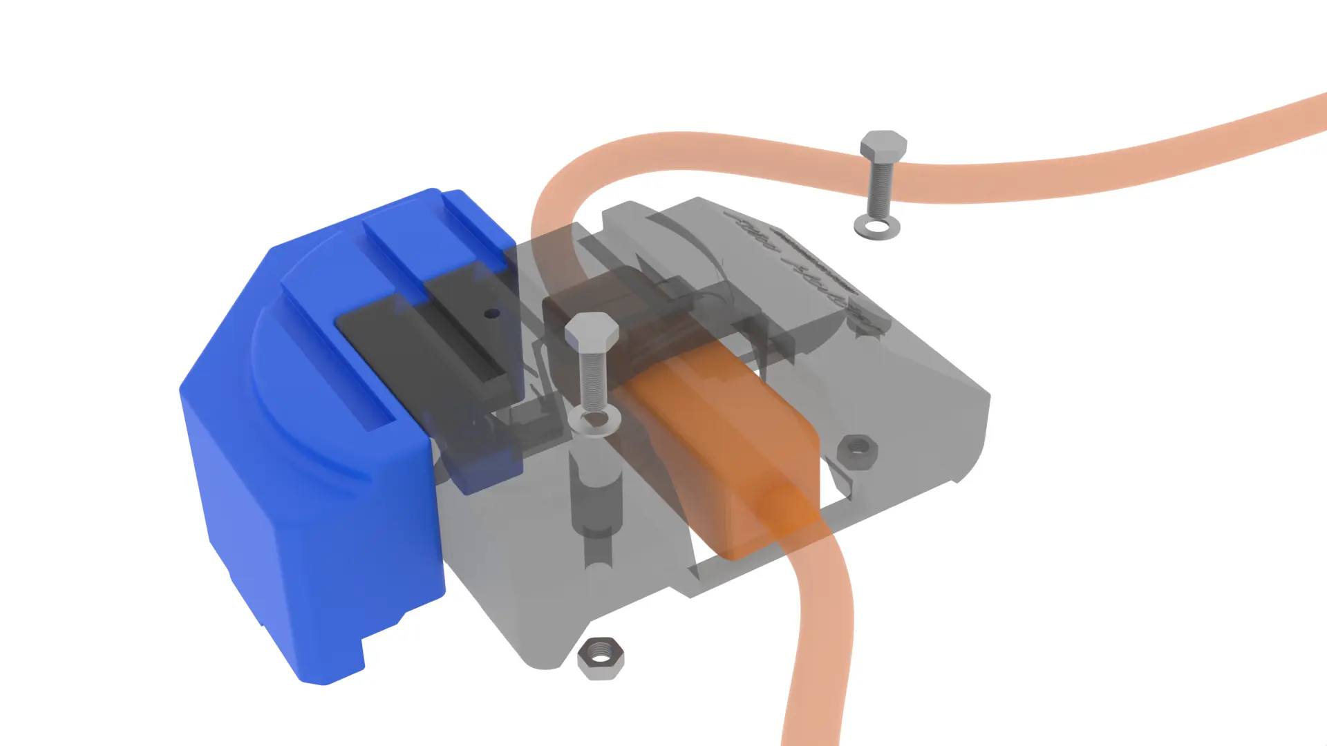
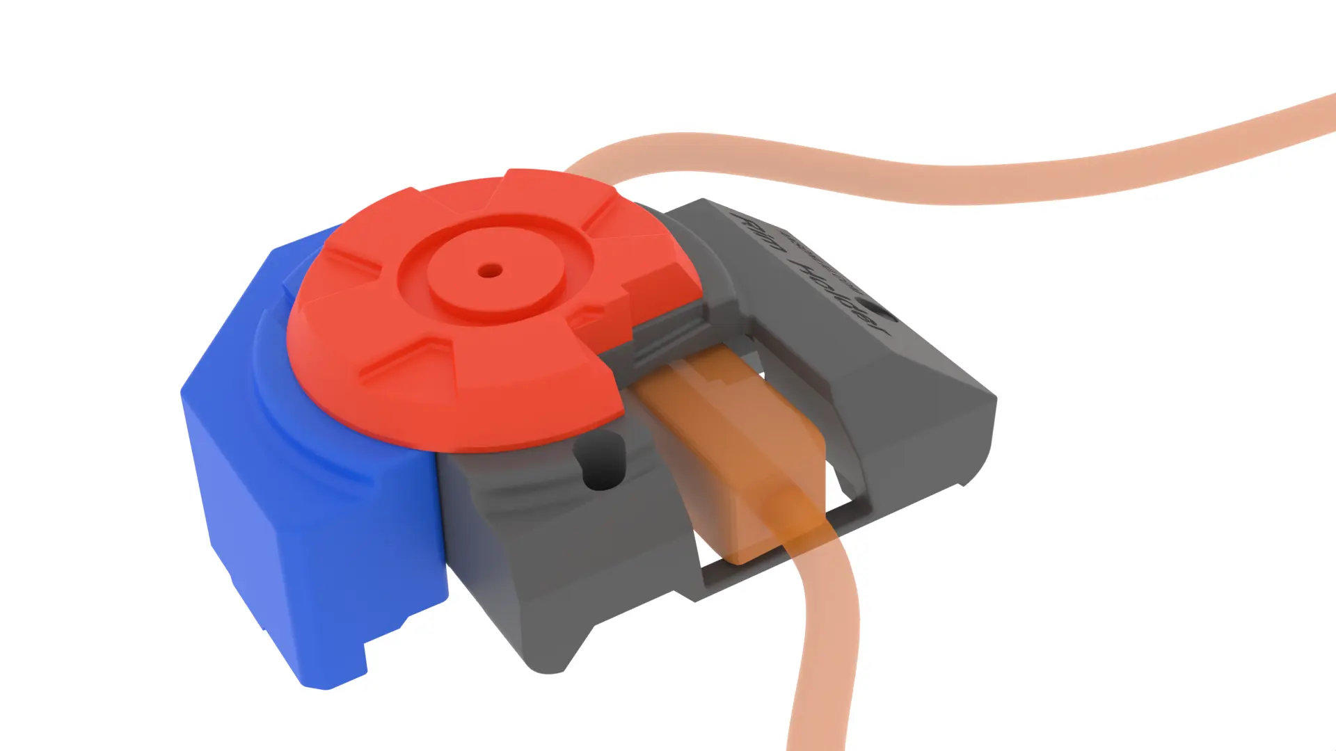
Tire Mount Disassembly
The parts may be shipped a single unit. Separate the parts in preparation for installation in the vehicle. If the parts are already separated from each other, proceed to Tire Mount Assembly.
-
Completely unscrew the Universal Tire Hold Down (and M8 bolt) from the top circular piece (Piece 3).
-
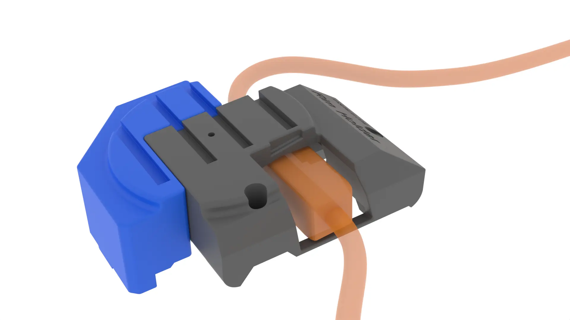
Piece 3 interlocks with the bottom 2 mount pieces with horizontal grooves running from left to right. Slide Piece 3 to the left until Piece 3 leaves the bottom 2 pieces as seen in the animation above.
-
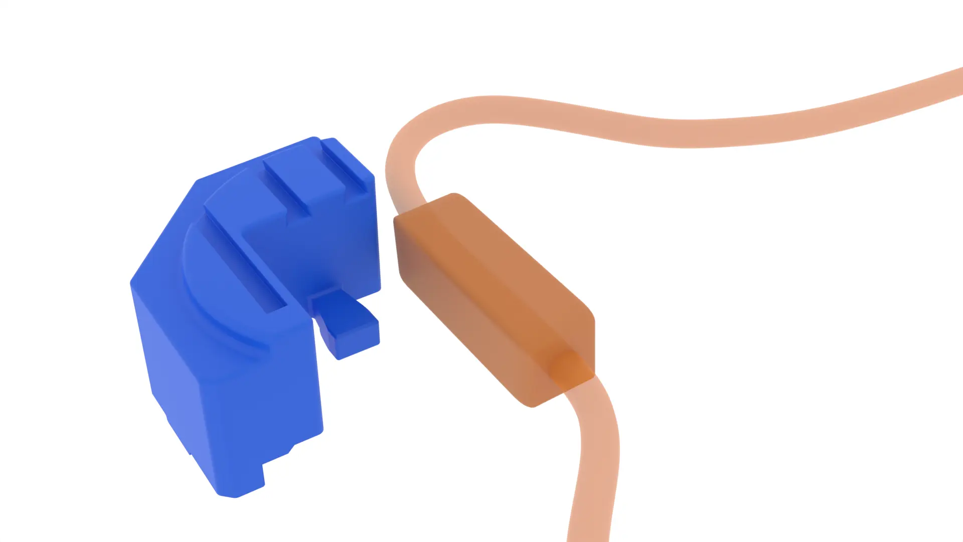
The rectangular piece (Piece 1) interlocks with the semi circular piece (Piece 2) with a groove on the underside of the pieces. Slide the Piece 1 upwards from Piece 2 until the two pieces separate as seen in the animation above.
-
Unscrew and remove two M10 nuts on the underside of Piece 1.
-
Remove two M10 bolts and washers from Piece 1.
Tire Mount Assembly
-
Slide Part 2 (labeled “2”) from left to right against the metal bracket underneath the power connector. The tongue on Part 2 fits underneath the metal bracket’s raised ridge.
↘️ Tilt Part 2 downwards towards the bracket (inboard) while ➡️ sliding the toungue underneath the bracket.
-
Lower Part 1 (labeled “1a/1b”) from above over the power connector and metal bracket. Part 1 bottom should be flat against top of the the metal bracket.
-
Reconnect the orange power connector. Flip the white lever down. Pop the black clip back into the white lever.
-
Place a M10 washer over each of the two M10 bolts.
-
Insert the M10 bolts through two holes on the front and right sides of Piece 1. The shorter bolt fits in the front.
-
Tighten the two bolts to the metal bracket with two M10 nuts on the bottom face of the metal bracket.
-
Slide Part 3 over Part 1 and Part 2 from the left. The grooves in the parts should fit into each other without excessive force.
If Part 3 will not slide in due to Part 1 and Part 2 top surfaces not being level, you can firmly secure Part 1 with bolts after sliding on Part 2 and Part 3. The bolts do not need a death grip as long as the serrated nut bites into the bracket to prevent loosening! Top surfaces not being level is likely due to car manufacturing variation. You will need to remember to remove the bolts before sliding off Part 3 in the future.
🩹 The non-metal parts in this kit can be patched with super glue.
Spare Tire
- Lower your spare tire centered above Part 3 onto the mount. The tire rim center bore surface should be flat against Part 3. You may need to flip the tire to the other side to get an acceptable fit. The tire orientation depends on the geometry of your spare tire. Try both orientations if the tire touches the cable.
⚠️ Spare rims with high offsets may touch the cable or sit very high. If this is the case, you may measure the additional height you need to raise the tire to clear the cable when placed “deep dish side down”. Then place a circular wood or dense foam piece with height equal to the measured additional height amount in between Part 3 and the rim as an additinal inside spacer. This may minimize the distance the cargo floor is ultimately raised by the spare tire. A longer tire hold down bolt may be needed after this modification.
⚙️ Part 3 may be customized by raising and lowering the top surface and making additinal cutouts made to better fit your specific tire. Customize and 3D print Part 3 using the released 3D model.
Tire Hold Down
⚠️ You should use a matching M8 threaded tire hold down for your spare tire. Part 1 and Part 3 are threaded for M8 bolts.
The Universal Tire Hold Down can be used if you do not have a matching hold down.
⚠️🔩 If you received multiple M8 bolts, you must try the fully threaded and shorter bolt first. Longer bolts can be tested if the shorter bolts do not get enough grip. Test longer bolts when Part 1 is NOT attached to Part 2. If the bolt sticks out of the bolt hole underneath Part 1, the bolt is too long and must cut shorter.
⚠️🔩 Partially threaded bolts should only be used if Part 3 has an unthreaded bolt hole. Part 3 - low profile has an unthreaded bolt hole. Screwing partially threaded bolts into threaded parts will wear out threads and preclude use of shorter bolts in the future.
-
If your kit came with multiple Tire Hold Down Handles and Tire Hold Down Rings, remove all handles and rings except the single handle and ring that match your center bore size. The extra parts are for future use if you get a new spare tire rim.
-
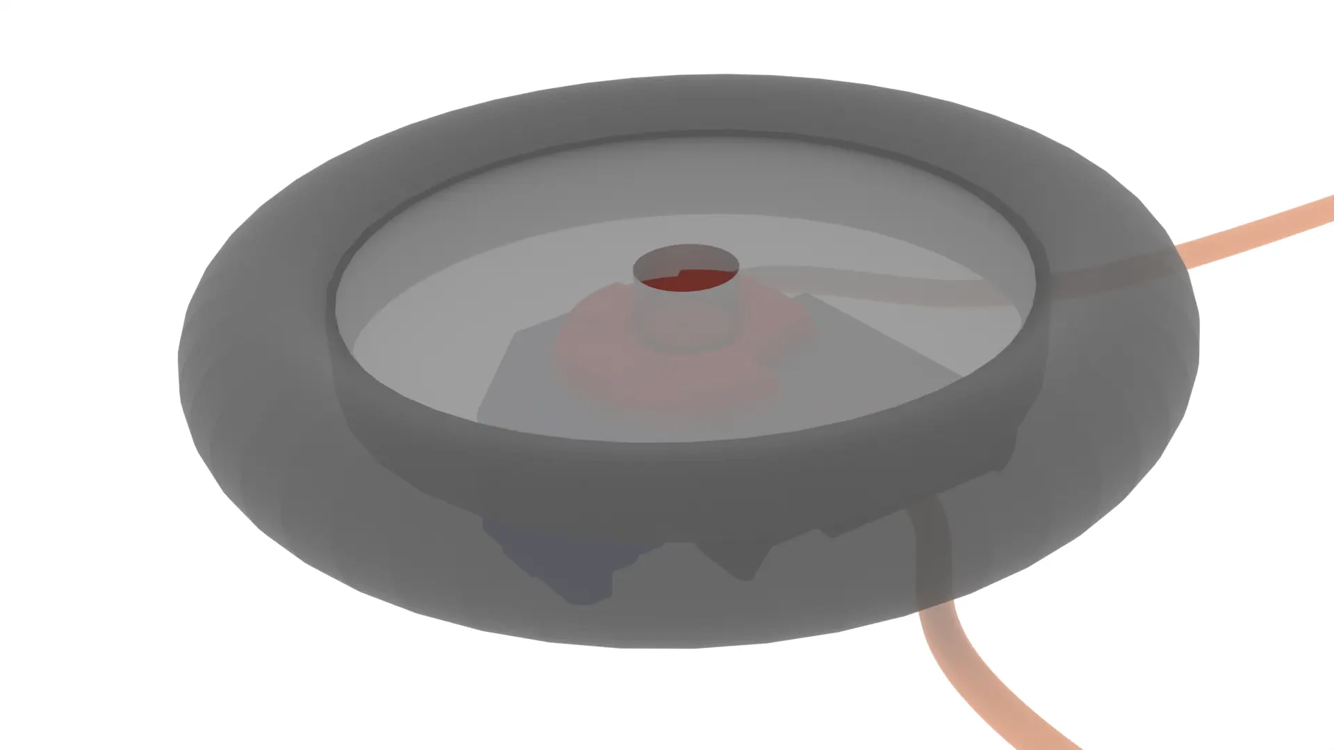
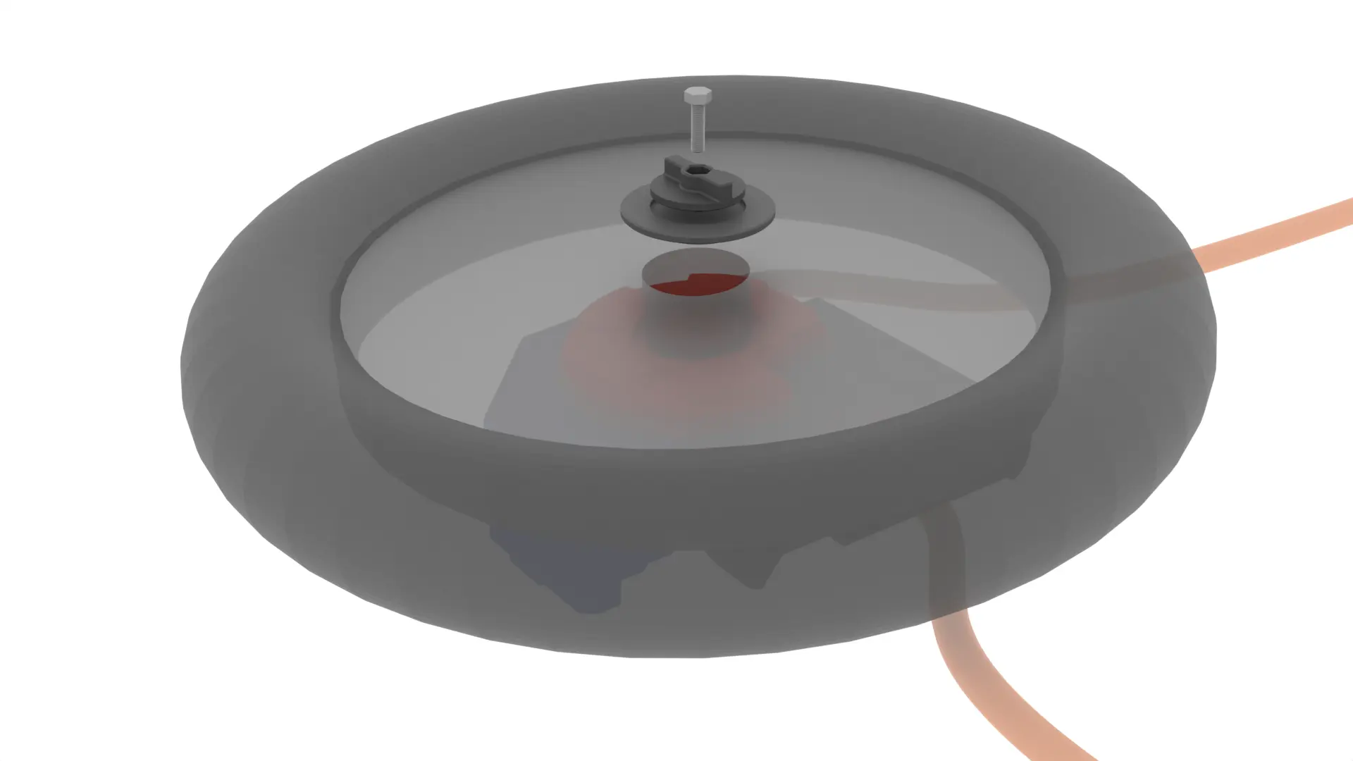
Insert the M8 bolt into the Tire Hold Down Handle so that the hex head of the bolt fits into the hex cutout in the handle.
-
Insert the Tire Hold Down Ring into the tire rim center bore hole from above.
-
Insert the Tire Hold Down Handle with M8 bolt into the Tire Hold Down Ring. The flat surfaces of the handle will be flat against the interior circular cutout of the hold down ring.
-
Finger tighten the hold down handle by turning the handle clockwise and applying downward pressure to the hold down ring. Stop tightening the handle when it is firm and resistance is encountered. Do not overtighten the handle or else Part 1 and Part 3 threads will be stripped.
-
If there is excessive play in the tire, repeat the previous step.
The plastic threads in Part 1 are sufficient to hold the tire in place. If you strip the plastic threads in Part 1, the M8 nut cutout on the bottom of the Part 1 may be enlarged to fit a M8 nut for an additional fastening point but this is untested.
Cargo Deck Spacer
-
Measure the vertical distance between the highest point on the tire and the top surface of the plastic cargo deck floor on the left or right. This vertical distance (typically 1-2”) is the thickness of the spacer needed for your combination of spare tire and vehicle.
-
Make or buy the spacer as described on the Cargo Riser store page.
-
Put the spacer on top of the cargo deck.
Finishing Up
-
Put the cargo floor on top of the spacer.
-
If you have a jack for your vehicle, the jack fits in the plastic cargo deck slot with the rubber band as a latch.
-
The Tire Puncture Kit consisting of a air compressor and tire sealant can be either removed from the car or placed under the cargo floor.
Additional vehicle accessories for the jack assembly, Tire Puncture Kit, and dashcam can be found in my released vehicle accessories collection and are available for custom order on the Store.