<?xml version="1.0" encoding="utf-8"?><feed xmlns="http://www.w3.org/2005/Atom" xml:lang="en-US"><generator uri="https://jekyllrb.com/" version="3.10.0">Jekyll</generator><link href="https://ansonliu.com/atom.xml" rel="self" type="application/atom+xml" /><link href="https://ansonliu.com/" rel="alternate" type="text/html" hreflang="en-US" /><updated>2026-05-07T04:31:15+00:00</updated><id>https://ansonliu.com/atom.xml</id><title type="html">Anson Liu</title><subtitle>Software design, 3D printing, and outdoor adventures</subtitle><author><name>Anson Liu</name></author><entry><title type="html">Mountains Majesty: On the Summit with John Fielder exhibit at History Colorado Center in Denver, Colorado</title><link href="https://ansonliu.com/2026/05/mountains-majesty-history-colorado-denver-exhibit/" rel="alternate" type="text/html" title="Mountains Majesty: On the Summit with John Fielder exhibit at History Colorado Center in Denver, Colorado" /><published>2026-05-06T00:00:00+00:00</published><updated>2026-05-06T00:00:00+00:00</updated><id>https://ansonliu.com/2026/05/mountains-majesty-history-colorado-denver-exhibit</id><content type="html" xml:base="https://ansonliu.com/2026/05/mountains-majesty-history-colorado-denver-exhibit/"><![CDATA[<p><img src="/wp-content/uploads/2026/05/history-colorado-majesty-mountains-john-fielder-exhibit1.webp" alt="Colorado 3D topographic map model as exhibit locator" /></p>

<p>My <a href="https://www.printables.com/model/529030-colorado-usa-co-topographic-map-with-hydrographic">Colorado 3D Topographic Maps</a> are used as supporting locator maps at the <a href="https://www.historycolorado.org/exhibit/mountains-majesty"><strong>Mountains Majesty: On the Summit with John Fielder exhibit</strong></a> <strong>at the History Colorado Center in Denver, Colorado</strong>.</p>

<p><img src="/wp-content/uploads/2026/05/history-colorado-majesty-mountains-john-fielder-exhibit2.webp" alt="Colorado 3D Topographic Maps supporting locator maps at the exhibit" /></p>

<p>These maps were printed in multiple colors presenting a light base map and dark rivers. Labels were placed on the map depicting the locations of John Fielder’s nature photos so that viewers can spatially visualize where the mountains are in the state.</p>

<p>The exhibit will be shown from JAN 24, 2026 - JAN 10, 2027</p>

<p><img src="/wp-content/uploads/2026/05/history-colorado-majesty-mountains-john-fielder-exhibit3.webp" alt="Displayed Colorado 3D topographic locator map" /></p>

<p><img src="/wp-content/uploads/2026/05/history-colorado-majesty-mountains-john-fielder-exhibit4.webp" alt="Displayed Colorado 3D topographic locator map with photo labels" /></p>

<p>These displayed Colorado maps were printed by the awesome Jordan Proctor (<a href="https://www.printables.com/@JordanProctorDesigns">JP Designs</a>), a photographer and designer whose original work can be viewed at <a href="https://www.etsy.com/shop/JPDesignsOfficial">https://www.etsy.com/shop/JPDesignsOfficial</a>. JP Designs is also a licensed seller of my 3D topographic map collection.</p>

<p>The design and development of these unique 3D maps were made possible by the contributions of open data, open source software, and my supporters.</p>

<p>You can download and print your own topographic map of Colorado and other states in the USA for free from <a href="https://ansonliu.com/maps">my website</a> or <a href="https://www.printables.com/@ansonl">Printables</a>.</p>

<p><a href="https://www.printables.com/model/529030-colorado-usa-co-topographic-map-with-hydrographic">Colorado USA (CO) Topographic Map with Hydrographic Features - Printables</a></p>

<p><img src="/wp-content/uploads/2026/05/history-colorado-mountains-majesty-fullpage.webp" alt="History Colorado Mountains Majesty exhibit page" /></p>

<p><a href="mailto:support@ansonliu.com">Contact me</a> or one of my <a href="https://ansonliu.com/store/other-designs/#licensed-sellers">licensed sellers</a> to get a map created.</p>]]></content><author><name>Anson Liu</name></author><category term="development" /><category term="3d printing" /><category term="maps" /><category term="printables" /><category term="colorado" /><summary type="html"><![CDATA[My [Colorado 3D Topographic Maps](https://www.printables.com/model/529030-colorado-usa-co-topographic-map-with-hydrographic) are used as supporting locator maps at the [**Mountains Majesty: On the Summit with John Fielder exhibit**](https://www.historycolorado.org/exhibit/mountains-majesty) **at the History Colorado Center in Denver, Colorado**. ![Colorado 3D topographic map model as exhibit locator](/wp-content/uploads/2026/05/history-colorado-majesty-mountains-john-fielder-exhibit1.webp) These maps were printed in multiple colors presenting a light base map and dark rivers. Labels were placed on the map depicting the locations of John Fielder's nature photos so that viewers can spatially visualize where the mountains are in the state. The exhibit will be shown from JAN 24, 2026 - JAN 10, 2027 ![History Colorado Mountains Majesty exhibit page animated scroll](/wp-content/uploads/2026/05/history-colorado-mountains-majesty-scroll-stop-blue-fade-loop.webp)]]></summary></entry><entry><title type="html">Updating OEM Dahua NVR and IP Cameras and removing region lock via firmware update</title><link href="https://ansonliu.com/2026/05/oem-dahua-nvr-ip-cam-remove-region-lock/" rel="alternate" type="text/html" title="Updating OEM Dahua NVR and IP Cameras and removing region lock via firmware update" /><published>2026-05-06T00:00:00+00:00</published><updated>2026-05-06T00:00:00+00:00</updated><id>https://ansonliu.com/2026/05/oem-dahua-nvr-ip-cam-remove-region-lock</id><content type="html" xml:base="https://ansonliu.com/2026/05/oem-dahua-nvr-ip-cam-remove-region-lock/"><![CDATA[<p>I recently got a set of 10 Dahua IP eyeball cameras and 16 port PoE NVR.</p>

<p>The camera and NVR are actually white branded Dahua which is an OEM brand for other vendors selling IP cams and NVRs. The previous owner got these before <a href="https://en.wikipedia.org/wiki/Dahua_Technology">Dahua</a> was banned from the USA and transitioned the USA side of the business to Lorex/Skywatch based in Taiwan.</p>

<h2 id="nvr">NVR</h2>

<p>My NVR model:</p>
<div class="language-plaintext highlighter-rouge"><div class="highlight"><pre class="highlight"><code>16 Channel 1U 2HDDs 16PoE Network Video Recorder
16CH 2HDD 1U NETWORK VIDEO RECORDER

White label version
Model：DNVR4KL1602-16P2

Dahua version
Model: DHI-NVR4216-16P-4KS2L &lt;- L suffix indicates a revised model

Latest firmware: General_NVR4x-4KS2L_MultiLang_V4.003.0000000.1.R.240515.bin
</code></pre></div></div>

<h3 id="nvr-reset">NVR reset</h3>

<p>The NVR was initially locked with the previous owner’s password so I opened up the case and pressed the reset button on the motherboard while power cycling it. I held the reset button down until a beep played about 30 seconds after turning it on. The NVR rebooted and I was able to set it up like new.</p>

<p>The white branded NVR I have has buttons on the front like a 6 disc DVD or CD player but the buttons don’t seem to do anything when pressed.</p>

<p>The existing NVR software seemed to not be able to playback recorded footage which you can only access through the web UI.</p>

<h3 id="nvr-firmware-update">NVR firmware update</h3>

<p>After some trial and error I found the latest firmware to be <code class="language-plaintext highlighter-rouge">General_NVR4x-4KS2L_MultiLang_V4.003.0000000.1.R.240515.bin</code> which you can find online. This is the generic version of the firmware without Dahua branding in the web interface.</p>

<p>This newer firmware built in 2024 has fixed the playback issue from earlier so recording footage can be viewed in the web UI.</p>

<p>You can turn off P2P which is unnecessary for the function of the NVR and IP cams.</p>

<p>I believe that the previous owner got the white branded NVR from Premium Security Solutions (PSS). The folks at PSS were nice enough to send me a copy of the latest firmware mentioned above.</p>

<h2 id="ip-camera">IP camera</h2>

<p>My IP camera model:</p>
<div class="language-plaintext highlighter-rouge"><div class="highlight"><pre class="highlight"><code>8MP WDR Eyeball Network CAMERA

White label version
Model：DNC8TDAI3in1-FC-AD

Dahua version
Name: WizSense 3 Series (Lite AI) HX38XX chip (dalton)
Model: IPC-HDW3841EM-AS, IPC-HDW3841EM-S ??

Latest firmwares: 
General_IPC-HX3XXX-Dalton_MultiLang_PN_Stream3_V2.820.0000000.32.R.250110.bin
DH_IPC-HX3XXX-Dalton_MultiLang_PN_Stream3_V2.820.0000000.32.R.250110.bin
</code></pre></div></div>

<h3 id="ip-camera-reset">IP camera reset</h3>

<p>After the NVR was reset, the IP cameras were still locked with the previous password and there isn’t a supported way to reset them remotely. The cameras I had look like the one below:</p>

<p><img src="/wp-content/uploads/2026/05/dahua-camera.webp" alt="Dahua 8MP WDR Eyeball Network CAMERA Tioc" /></p>

<p>On the 6 oclock position of the camera, there are 2 screws holding an access cover that you can remove to expose a reset button. Hold the reset button for 30 seconds to factory reset the camera.</p>

<p>If you cannot remove the camera from the mount due to a seized T10 torx set screw as several of mine were, you can either:</p>

<ul>
  <li>Manhandle the camera orientation to expose the bottom access hatch</li>
  <li>Drill out the torx screw, thread the hole with a M5 (5mm) thread, and replace with a 5mm long M5 set screw</li>
</ul>

<p>I tried both and option 1 is much better.</p>

<p>Once the camera has rebooted which will happen automatically after the reset, you will see it show up in the NVR camera menu. You can either set the new credentials with the NVR or set them through the IP cam web UI by navigating to the IP camera’s IP address. You need to toggle Bridge mode in the NVR settings to expose the PoE ports to your main network that the NVR is attached to.</p>

<h3 id="ip-camera-firmware-update">IP camera firmware update</h3>

<p>Typing the camera model and serial number into the Dahua website showed a “not found” error so I tried looking around the Dahua website for similar products.</p>

<p>There is a similar product line listed which has a <code class="language-plaintext highlighter-rouge">Taurus</code> generation new firmware listed. However the cameras that I got were actually an older <code class="language-plaintext highlighter-rouge">Dalton</code> generation that looks identical but are not listed on the main website.</p>

<p>If you upload the wrong firmware to the camera, the camera will reboot after a few minutes and no change will occur.</p>

<p>The latest firmwares for Dalton cameras are <code class="language-plaintext highlighter-rouge">General_IPC-HX3XXX-Dalton_MultiLang_PN_Stream3_V2.820.0000000.32.R.250110.bin</code> and <code class="language-plaintext highlighter-rouge">DH_IPC-HX3XXX-Dalton_MultiLang_PN_Stream3_V2.820.0000000.32.R.250110.bin</code> for the Generic and Dahua branded web UI respectively.</p>

<p>You need to update with the Generic <code class="language-plaintext highlighter-rouge">General</code> firmware first to remove the region lock. Then you can update with the Dahua branded <code class="language-plaintext highlighter-rouge">DH</code> firmware.</p>

<h2 id="generic-vs-dahua-firmware-differences">Generic vs Dahua firmware differences</h2>

<p>The difference in Generic and Dahua firmware from a user perspective is branding and update servers. The web UI will say “IP CAM” vs “Dahua” with different logos.</p>

<p><img src="/wp-content/uploads/2026/05/dh-branded-login.webp" alt="dahua branded login" /></p>

<p>The Generic firmwares that I installed always say the latest version is installed. Even downgrading to older Generic firmware versions says that the latest version is installed so it’s not clear if the checked update server is invalid or unreachable.</p>

<p><img src="/wp-content/uploads/2026/05/general-firmware-unable-to-check-update.webp" alt="generic firmware update" /></p>

<p>The Dahua version can successfully check for updates.</p>

<p><img src="/wp-content/uploads/2026/05/dh-firmware-gets-update.webp" alt="dahua firmware update" /></p>

<p>The generic firmware that I had on the NVR said a similar “no updates found” and I didn’t try loading Dahua branded firmware onto the NVR. I assume the same update behavior happens.</p>

<h2 id="finding-the-firmware">Finding the firmware</h2>

<p>In addition to Dahua and reseller websites, I used the directory listings at https://files.dahuatech.support/ and https://files.dahua.support/ to find the latest firmwares.</p>]]></content><author><name>Anson Liu</name></author><category term="development" /><category term="cctv" /><summary type="html"><![CDATA[You can remove the generic vendor's region lock and update the firmware on OEM Dahua IP cameras via the generic `General` firmware. Removing the region lock with generic firmware also allows loading of Dahua branded firmware onto a white labeled model. ![Dahua 8MP WDR Eyeball Network CAMERA Tioc](/wp-content/uploads/2026/05/dahua-camera.webp)]]></summary></entry><entry><title type="html">3D Maps and Models available on Printables and not on MakerWorld</title><link href="https://ansonliu.com/2026/03/makerworld-account-ban/" rel="alternate" type="text/html" title="3D Maps and Models available on Printables and not on MakerWorld" /><published>2026-03-03T00:00:00+00:00</published><updated>2026-03-03T00:00:00+00:00</updated><id>https://ansonliu.com/2026/03/makerworld-account-ban</id><content type="html" xml:base="https://ansonliu.com/2026/03/makerworld-account-ban/"><![CDATA[<p><img src="/assets/images/portfolio/printables-scroll-thumbnail.webp" alt="Printables scroll" /></p>

<p>My maps and models continue to be available <a href="https://www.printables.com/@ansonl">Printables</a>. You will find my latest uploads and updates on Printables but not on MakerWorld.</p>

<p><em>The <a href="https://www.printables.com/model/656330-china-mainlandhainantaiwan-3d-topo-relief-map-with">3D map of China</a> got reported on MakerWorld so the account got banned and models delisted. You will find my models previously available on MakerWorld on Printables instead.</em></p>

<p>I try to upload my models to both Printables and MakerWorld already so it’s business as usual if you have used Printables before. All of my map variants are already on Printables versus other sites due to Printables’ much better upload policy and larger model size limit. If you can’t find one of the my models due to a broken link, let me know so I can re-upload it to Printables.</p>

<p>If you’re wondering how to print the maps and models without a “print profile”, all you need to do is match your slicer settings to my listed <a href="/maps/print-settings/">3D print settings</a>. The concept of a “print profile” that MakerWorld promotes is merely a model file with some user settable printing settings attached in a 3MF and not a secret that magically makes a certain model print perfect on a certain printer.</p>

<p>I’ll consider putting my models back on that site if/when the account is reinstated.</p>]]></content><author><name>Anson Liu</name></author><category term="development" /><category term="3d printing" /><category term="maps" /><category term="bambu" /><category term="makerworld" /><category term="printables" /><summary type="html"><![CDATA[My maps and models continue to be available [Printables](https://www.printables.com/@ansonl). You will find my latest uploads and updates on Printables but not on MakerWorld. ![Printables scroll](/assets/images/portfolio/printables-scroll-thumbnail.webp) *The [3D map of China](https://www.printables.com/model/656330-china-mainlandhainantaiwan-3d-topo-relief-map-with) got reported on MakerWorld so the account got banned and models delisted. You will find my models previously available on MakerWorld on Printables instead.*]]></summary></entry><entry><title type="html">3D Map Feature Modifier (MFM) Post Processor</title><link href="https://ansonliu.com/2025/03/map-feature-modifier-3d-printed-isolines/" rel="alternate" type="text/html" title="3D Map Feature Modifier (MFM) Post Processor" /><published>2025-03-04T00:00:00+00:00</published><updated>2025-03-04T00:00:00+00:00</updated><id>https://ansonliu.com/2025/03/map-feature-modifier-3d-printed-isolines</id><content type="html" xml:base="https://ansonliu.com/2025/03/map-feature-modifier-3d-printed-isolines/"><![CDATA[<p>You can add elevation contour lines and color changes to your 3D printed maps with a new script that I created.</p>

<p><img src="/wp-content/uploads/2025/03/MFM-header-short.webp" alt="MFM logo" /></p>

<p>The <a href="https://github.com/ansonl/mfm">Map Feature Modifier</a> (MFM) script is compatible with Prusaslicer, OrcaSlicer, and Bambu Studio. It is also open source and free to use! Download it <a href="https://github.com/ansonl/mfm">here</a>.</p>

<video style="max-width:100%; height:auto;" width="768" height="432" autoplay="" loop="" muted="" playsinline="">
  <source src="/wp-content/uploads/2025/03/MFM-preview-720p-10fps.webm" type="video/webm" />
</video>

<h2 id="elevation-contour-lines">Elevation Contour Lines</h2>

<p>Elevations contour lines (also known as isolines) show a path of constant elevation on a height map.</p>

<p><img src="/wp-content/uploads/2025/03/map-contour-lines.webp" alt="map contour lines" /></p>

<h2 id="symbology-elevation-scale">Symbology Elevation Scale</h2>

<p>Usually height on a map is colored along a scale as seen below.</p>

<dl>
  <dt><img src="/wp-content/uploads/2025/03/map-color-scale.webp" alt="map color scale" /></dt>
  <dd><em>ESRI</em></dd>
</dl>

<h2 id="bringing-cartographic-map-features-to-3d-printing">Bringing Cartographic Map Features to 3D Printing</h2>

<p>Now you can add both of these features into a 3D printed map with the free Map Feature Modifier!</p>

<p>It is optimized for use with my free <a href="/maps">3D printable maps</a>. It even works on models that are not maps so you can add layered color changes in creative ways to other objects.</p>

<p>I made a <a href="https://www.youtube.com/watch?v=3BnW-QVdqKM">tutorial video</a> showing how to use the Map Feature Modifier. All of the steps are also written to follow at your own pace on the GitHub <a href="https://github.com/ansonl/mfm">repo</a>.</p>

<iframe width="560" height="315" src="https://www.youtube.com/embed/3BnW-QVdqKM?si=B7kV8L-rIug6GStB" title="YouTube video player" frameborder="0" allow="accelerometer; autoplay; clipboard-write; encrypted-media; gyroscope; picture-in-picture; web-share" referrerpolicy="strict-origin-when-cross-origin" allowfullscreen=""></iframe>

<p>Normally I would write the content of the video in a post but I just started a new job and don’t have a lot of time lately so the video and Github repo documentation will need to suffice for now.</p>

<h3 id="how-it-works">How it works</h3>

<p>I go into more depth on how the script works in the <a href="https://youtu.be/3BnW-QVdqKM?si=69PDapS5IXn_NaQ3&amp;t=753">internals</a> portion at the end of the MFM tutorial youtube video. I’ve written a short quick explanation below.</p>

<p>Initially I tried simply replacing the <code class="language-plaintext highlighter-rouge">T</code> tool indices on spaced out layers to create the isolines but that leads to an oil slick effect when the top surface coincides with an isoline layer.</p>

<p>Instead of being layer aware, I needed to increase of the granularity of the script to be feature aware. Each printing feature is tracked so that only the outer walls (or other user selected feature type) is recolored to create isolines. The order of the printing features must also be altered to print all the outer walls at once before switching to print the inner walls or other features so that toolchanges and color swaps are kept to a minimum.</p>

<p>The existing toolchange and prime tower movements are also reused on demand so that new toolchanges will use the prime tower and toolchange to avoid wasted material and time from flushing.</p>

<p>Map Feature Modifier ended up becoming a framework that can extract and reorder G-code into relocatable and modifiable G-code segments akin to assembly <a href="https://www.youtube.com/watch?v=ajGX7odA87k&amp;t=1868s">gadgets</a>.</p>

<p>It can run either within a slicer as a post processing script, a command line program, or a GUI app. I also added the feature for the GUI app to handle Plate Sliced 3MF which is sliced G-code that is compressed into a 3MF which is more friendly for normal users to import and preview the processed 3MF in the slicer.</p>

<h2 id="thanks">Thanks</h2>

<p>A big thank you the below individuals as well as the 3D printing community.</p>

<ul>
  <li>
    <p>Chris Harding for his work on <a href="https://github.com/ChHarding/TouchTerrain_for_CAGEO">TouchTerrain</a> and letting me contribute to the project.</p>
  </li>
  <li>
    <p>Brian Kelley from Colorado for kickstarting my initial work on Map Feature Modifier.</p>
  </li>
  <li>
    <p>Joseph Sanzo and Khor Hon Wei for trusting me with their 3D printers as guinea pigs.</p>
  </li>
  <li>
    <p><a href="https://toybox.com/">Toybox Labs</a> for filament to test.</p>
  </li>
</ul>]]></content><author><name>Anson Liu</name></author><category term="development" /><category term="3d printing" /><category term="maps" /><category term="prusaslicer" /><category term="bambu" /><category term="orcaslicer" /><summary type="html"><![CDATA[Add elevation contour lines and color changes to your 3D printed maps with the free [Map Feature Modifier](https://github.com/ansonl/mfm) app! I have posted a [tutorial video](https://www.youtube.com/watch?v=3BnW-QVdqKM) that you can watch to see what is possible with the Map Feature Modifier!]]></summary><media:thumbnail xmlns:media="http://search.yahoo.com/mrss/" url="https://ansonliu.com/wp-content/uploads/2025/03/ca-topo-map-banner.webp" /><media:content medium="image" url="https://ansonliu.com/wp-content/uploads/2025/03/ca-topo-map-banner.webp" xmlns:media="http://search.yahoo.com/mrss/" /></entry><entry><title type="html">Adaptive Start G-code for Dual Extruder Printers with Cura</title><link href="https://ansonliu.com/2024/10/cura-adaptive-dual-extruder-start-gcode/" rel="alternate" type="text/html" title="Adaptive Start G-code for Dual Extruder Printers with Cura" /><published>2024-10-08T00:00:00+00:00</published><updated>2024-10-08T00:00:00+00:00</updated><id>https://ansonliu.com/2024/10/cura-adaptive-dual-extruder-start-gcode</id><content type="html" xml:base="https://ansonliu.com/2024/10/cura-adaptive-dual-extruder-start-gcode/"><![CDATA[<p>Choosing a reliable start G-code that primes a dual extruder printer is difficult. There are different extruder prime techniques and my <a href="https://github.com/ansonl/DXU/blob/master/AL-DXUv2/start-end-gcode/cura-adaptive-start-gcode-dual-extruder.gcode">adaptive priming start G-code</a> for Cura uses a mix of these techniques to properly prime the most single/dual nozzle printers.</p>

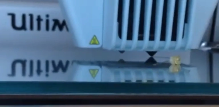
<video style="max-width:100%; height:auto;" width="768" height="432" autoplay="" loop="" muted="" playsinline="">
  <source src="/wp-content/uploads/2024/10/ultimaker-dxuv2-prime-video.webm" type="video/webm" />
</video>

<h2 id="prime-techniques">Prime Techniques</h2>

<p>Too little priming leads to inconsistent extrusion and lack of bed adhesion during the first minute of a print before the filament catches up to the nozzle tip.</p>

<p>Too much extrusion leads to blobs sticking to the nozzle and wasted print area.</p>

<p>FDM 3D printing priming techniques have evolved alongside 3D printer hardware to reach higher success rates for extruder priming.</p>

<h3 id="prime-blob">Prime Blob</h3>

<p>The Prime Blob is an early technique to quickly unclog and prime the nozzle in a few steps.</p>

<ol>
  <li>
    <p>The nozzle is initially raised far above the bed while heating up.</p>
  </li>
  <li>
    <p>The extruder quickly pushes long length of filament out of the nozzle to create a stream of plastic. The pressure and speed of this rapid extrusion dislodges any stuck plastic on the nozzle to join the plastic stream.</p>
  </li>
  <li>
    <p>The nozzle is simultaneously lowered to the printing layer height and initial printing location.</p>
  </li>
</ol>

<p>Ideally the extruded plastic sticks onto the bed and not the nozzle. When nozzle cannot travel off the bed, the prime blob is considered unreliable because the plastic may not contact or stick to the bed early enough which leads to a line of purged plastic loosely sticking to the bed as the nozzle travels to the initial printing location.</p>

<p><img src="/wp-content/uploads/2024/10/ultimaker-prime-blob.webp" alt="ultimaker prime blob" /></p>

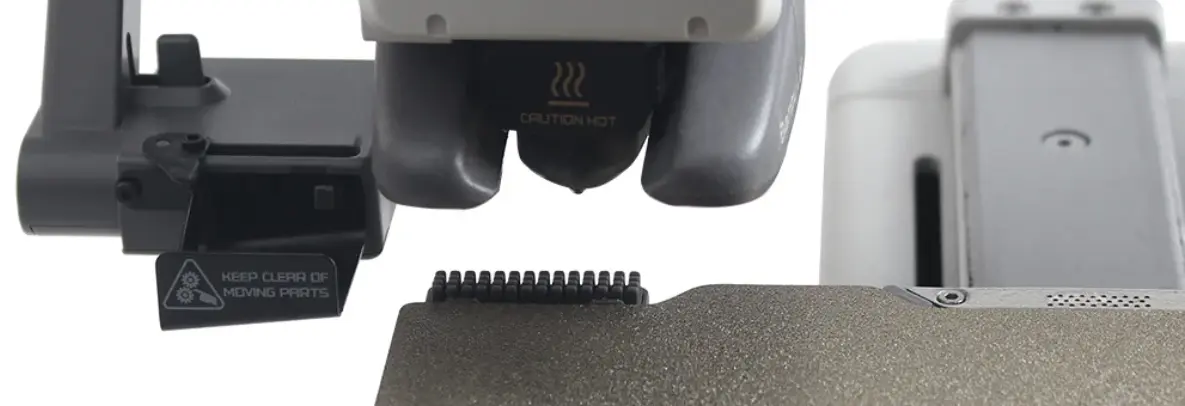
<p>The prime blob was most notably used by older Ultimaker printers and explicit generation of prime blob G-code is disabled by default in newer Cura versions.</p>

<p>Some printers such as those made by Prusa and Bambu Labs have gantries that allow the nozzle to move out of the normally printable area. When the prime blob is ejected off to a location off the bed, the chance of failure where the blob is dragged along the bed by the nozzle is lower.</p>

<h3 id="prime-lines">Prime Lines</h3>

<p>Prime lines can be as simple as a single straight line, back and forth line sequences, or even a series of curves to try to shake off filament stuck to the nozzle at all angles.</p>

<ol>
  <li>
    <p>The nozzle is raised above the bed while heating up.</p>
  </li>
  <li>
    <p>The nozzle is lowered to the bed at a low height (such as the printing layer height).</p>
  </li>
  <li>
    <p>The nozzle moves along the prime line pattern while extruding plastic.</p>
  </li>
</ol>

<p><img src="/wp-content/uploads/2024/10/bambu-filament-calibration.webp" alt="bambu filament calibration prime line" /></p>

<p>Build plate materials and coatings have become more durable to high temperatures and formulated specifically for superior bed adhesion with the use of steel and PEI coated beds. Newer printers’ prime line routines omit step 1 and keep the nozzle lowered to the bed while heating up. Hot plastic that leaks out of the nozzle due to expansion and gravity sticks to the bed and has a low chance of sticking to the nozzle when the prime line is extruded.</p>

<h3 id="nozzle-cleaning">Nozzle Cleaning</h3>

<p>Nozzle cleaning is a more recent technique where the nozzle is run over scrubbers of disimilar material than the filament material.</p>

<p><img src="/wp-content/uploads/2024/10/bambu-nozzle-brush.webp" alt="bambu nozzle brush" /></p>

<p>When a scrubber is not available, some printers vary of distance between the nozzle and bed in an attempt to get built up plastic blobs to detach from the nozzle and stick on the bed. Typically the nozzle is heated up and lowered to touch the bed. The nozzle temperature is lowered to a standby temperature where the plastic is not liquid while the nozzle is slowly moved away from the hot bed. This nozzle movement away from the bed is usually in both the vertical and horizontal directions and the part cooling fan can be set to 100% speed to help cool and solidfy the plastic.</p>

<p><img src="/wp-content/uploads/2024/10/bambu-bed-wipe-zone.webp" alt="bambu bed nozzle cleaning wipe zone" /></p>

<p>Marlin supports the <a href="https://marlinfw.org/docs/gcode/G012.html">G12</a> command to invoke a preconfigured nozzle cleaning process.</p>

<h2 id="adaptive-priming-start-g-code-for-cura">Adaptive Priming Start G-code for Cura</h2>

<p>Interpreted commands in start G-code have been available in PrusaSlicer for years while Cura start G-codes have been forced to be hard coded in the past.</p>

<p>Previously, it was not possible for the start G-code to know which extruders were active, much less what the initial extruder index was. Dual extruder machine configurations in Cura often had repetitive “single” and “dual” machines where the only difference was the start G-code referencing different extruder indexes and priming different number of extruders. Multiple machine profiles in Cura to represent the same machine were hard to maintain, error prone, lagged the slicer, and reset the active print profile when switching between machines.</p>

<p>Cura 5.7.1 and later added support for interpreted variables and math operations in start G-code which opened up the path for smarter start G-code.</p>

<video style="max-width:100%; height:auto;" width="768" height="432" autoplay="" loop="" muted="" playsinline="">
 <source src="/wp-content/uploads/2024/10/cura-dual-extruder-adaptive-start-gcode-preview.webm" type="video/webm" />
</video>

<p>Cura start G-code can now use different values in response to slicer variable values through math and ternary operators.</p>

<p>Python syntax ternary operators are supported in start G-code:</p>

<div class="language-python highlighter-rouge"><div class="highlight"><pre class="highlight"><code><span class="n">a</span> <span class="k">if</span> <span class="n">condition</span> <span class="k">else</span> <span class="n">b</span>
</code></pre></div></div>

<p>When starting a dual material print, we want the initial extruder to prime last so that the nozzle pressure is immediately used to extrude on the first layer and the nozzle does not leak plastic while waiting to cool and heat. Before math and conditional start G-code, it was not possible to switch to the extruder that was not the initial extruder because we could only use the <code class="language-plaintext highlighter-rouge">initial_extruder_nr</code> value which was the opposite of the extruder we wanted. Now we can calculate the unused extruder index with a ternary or modulus operator.</p>

<pre><code class="language-gcode">T{0 if initial_extruder_nr&gt;0 else 1} ; switch to NOT initial_extruder_nr nozzle
</code></pre>

<p>A potentially serious issue with using a “dual” machine configuration for a single material print in the past was priming and leaving the unused nozzle on. Leaving a nozzle hot led to heat creep and burnt plastic which increases the risk of clogs. This also wasted energy and hampered part cooling. If we know that a nozzle will not be used, it is better to leave that heater off.</p>

<p>If we leave the unused nozzle off, we need to avoid heating and moving the extruder when that tool (nozzle) is selected. We can either use conditional statements to skip the prime movements for the unused nozzle or we can just set all <code class="language-plaintext highlighter-rouge">E</code> axis movements to <code class="language-plaintext highlighter-rouge">0</code> during the unused nozzle’s prime routine. I found it more readable to do the second when the nozzle was unused.</p>

<pre><code class="language-gcode">M104 T{0 if initial_extruder_nr&gt;0 else 1} S{material_final_print_temperature if extruders_enabled_count &gt; 1 else 0, 0 if initial_extruder_nr&gt;0 else 1} ; Start heating up the NOT initial extruder

G1 X{140-125 if initial_extruder_nr&gt;0 else 100+125} E{switch_extruder_retraction_amount if extruders_enabled_count &gt; 1 else 0, initial_extruder_nr} F1500
</code></pre>

<p>In the above G-code, the tool is heated up and extrudes only if <code class="language-plaintext highlighter-rouge">extruders_enabled_count &gt; 1</code>. In a dual extruder machine where we always prime the extruder that is NOT the <code class="language-plaintext highlighter-rouge">initial_extruder_nr</code> first, <code class="language-plaintext highlighter-rouge">extruders_enabled_count &gt; 1</code> evaluating to <code class="language-plaintext highlighter-rouge">False</code> means that only one extruder will be used in the print and that used extruder’s index is <code class="language-plaintext highlighter-rouge">initial_extruder_nr</code>. Therefore we set the temperature and <code class="language-plaintext highlighter-rouge">E</code> axis movements to <code class="language-plaintext highlighter-rouge">0</code> for all commands in the prime routine for the never used extruder that is NOT the <code class="language-plaintext highlighter-rouge">initial_extruder_nr</code>.</p>

<p>I use <code class="language-plaintext highlighter-rouge">machine_width</code> to prime each extruder as close to the edge of the printable area as possible regardless of machine size.</p>

<p>I use <code class="language-plaintext highlighter-rouge">switch_extruder_retraction_amount</code> to prime at least the long retraction distance for each extruder to reset all filament to known locations within the print train.</p>

<h3 id="dxuv2-start-g-code-features">DXUv2 Start G-code Features</h3>

<p>I created the <a href="https://github.com/ansonl/DXU/blob/master/AL-DXUv2/start-end-gcode/cura-adaptive-start-gcode-dual-extruder.gcode">adaptive dual extruder start G-code</a> to prime both nozzles on my dual extruder Ultimaker 2 printer with the DXUv2 upgrade. A preview of the start G-code for both nozzle is depicted below. PrusaSlicer G-code Viewer was used for this preview because it has <a href="https://marlinfw.org/docs/gcode/G002-G003.html">arc command</a> support while the Ultimaker Cura preview does not. When slicing a model, the Cura preview reflects the G-code produced by the “Cura” side of the slicer which does not include start G-code or post processing changes so the G=code must be exported and dragged back into Cura for an accurate preview.</p>

<video style="max-width:100%; height:auto;" width="768" height="432" autoplay="" loop="" muted="" playsinline="">
 <source src="/wp-content/uploads/2024/10/prusa-dual-extruder-adaptive-start-gcode-preview.webm" type="video/webm" />
</video>

<p>I included certain characteristics in the start G-code to make the prime routine of dual and single nozzles as reliable as possible.</p>

<h4 id="reset-filament-location-prime-line">Reset Filament Location Prime Line</h4>

<p><img src="/wp-content/uploads/2024/10/long-retract-prime.webp" alt="long retract prime" /></p>

<p>The extruder that is NOT the initial extruder is primed first. The filament may have been retracted by <code class="language-plaintext highlighter-rouge">switch_extruder_retraction_amount</code> distance at the end of the last print. The nozzle is heated up and then lowers to the bed diagonally and extrudes filament by <code class="language-plaintext highlighter-rouge">switch_extruder_retraction_amount</code> to move the filament to the nozzle tip. Depending on the filament’s starting position within the print train, plastic may or may not actual extruded onto the bed (both of which are fine) which is why the nozzle continuously moves to maintain extruded prime line height.</p>

<h4 id="avoid-bed-corner-clip">Avoid Bed Corner Clip</h4>

<p><img src="/wp-content/uploads/2024/10/bed-clip-avoid.webp" alt="avoid bed clip" /></p>

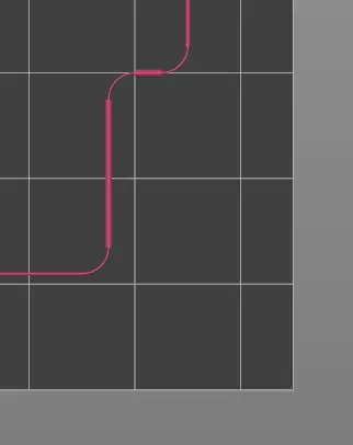
<p>The extruder moves around the exclusion zone of the Ultimaker bed clips in the corners of the printable area while extruding the whole time. Arc movements are used to smooth out the movement and wipe the nozzle from different angles.</p>

<h4 id="prime-line">Prime Line</h4>

<p><img src="/wp-content/uploads/2024/10/short-prime.webp" alt="prime line" /></p>

<p>The main prime line for the extruder is printed. After the first prime, the filament is almost guaranteed to be at the nozzle tip so we can get a stable prime line.</p>

<h4 id="break-line-and-raise">Break Line and Raise</h4>

<p><img src="/wp-content/uploads/2024/10/break-raise.webp" alt="prime line" /></p>

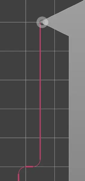
<p>The extruder moves quickly while close to the bed to break the prime line from the nozzle and then raises away from the bed in preparation to switch to the initial extruder. The extruder is cooled down to the standby temperature.</p>

<h4 id="initial-extruder-prime">Initial Extruder Prime</h4>

<p><img src="/wp-content/uploads/2024/10/second-prime-routine.webp" alt="initial extruder prime" /></p>

<p>The initial extruder is primed with a similar sequence that is flipped to the other side of the bed. The <strong>Reset Filament Location Prime Line</strong> is offset to not touch any extrusion by the previous extruder.</p>

<h4 id="prime-line-wipe-and-end-prime-location">Prime Line Wipe and End Prime Location</h4>

<p><img src="/wp-content/uploads/2024/10/end-prime-location.webp" alt="initial extruder prime" /></p>

<p>After the break line, a U turn is done with an arc to return the extruder as close to the origin as possible while avoiding the bed clip. The nozzle travels over the previous prime line and is raised slightly to take advantage at the crossing point to wipe the nozzle against previously laid down plastic.</p>

<h4 id="results">Results</h4>

<p><img src="/wp-content/uploads/2024/10/ultimaker-dxuv2-prime-bed-result.webp" alt="end result" /></p>

<p>I’ve had great results with this dual nozzle prime routine with very few failures (almost all due to existing user error). It saves time by not heating unused extruders and ensures that the initial extruder is always primed last.</p>

<p>The entire prime line is connected so it is easily removed as a single piece.</p>

<h4 id="possible-future-improvements">Possible Future Improvements</h4>

<p>I could heat up the nozzle while it is touching the bed instead of raised in the air. This has the drawback of burning a hole in PEI beds to expose the metal underneath that is within the printable area but could work for glass bed users.</p>

<h2 id="full-adaptive-dual-extruder-start-g-code">Full Adaptive Dual Extruder Start G-code</h2>

<p>My <a href="https://github.com/ansonl/DXU/blob/master/AL-DXUv2/start-end-gcode/cura-adaptive-start-gcode-dual-extruder.gcode">full adaptive dual extruder start G-code</a> is on GitHub as part of the <a href="https://github.com/ansonl/DXU/">DXUv2 project</a>. The start G-code as of 10/07/24 is:</p>

<pre><code class="language-gcode">; Octolapse variables
; Script based on an original created by tjjfvi (https://github.com/tjjfvi)
; An up-to-date version of the tjjfvi's original script can be found
; here:  https://csi.t6.fyi/
; Note - This script will only work in Cura V4.2 and above!
; --- Global Settings
; layer_height = {layer_height}
; smooth_spiralized_contours = {smooth_spiralized_contours}
; magic_mesh_surface_mode = {magic_mesh_surface_mode}
; machine_extruder_count = {machine_extruder_count}
; --- Single Extruder Settings
; speed_z_hop = {speed_z_hop}
; retraction_amount = {retraction_amount}
; retraction_hop = {retraction_hop}
; retraction_hop_enabled = {retraction_hop_enabled}
; retraction_enable = {retraction_enable}
; retraction_speed = {retraction_speed}
; retraction_retract_speed = {retraction_retract_speed}
; retraction_prime_speed = {retraction_prime_speed}
; speed_travel = {speed_travel}
; --- Multi-Extruder Settings
; speed_z_hop_0 = {speed_z_hop, 0}
; speed_z_hop_1 = {speed_z_hop, 1}
; retraction_amount_0 = {retraction_amount, 0}
; retraction_amount_1 = {retraction_amount, 1}
; retraction_hop_0 = {retraction_hop, 0}
; retraction_hop_1 = {retraction_hop, 1}
; retraction_hop_enabled_0 = {retraction_hop_enabled, 0}
; retraction_hop_enabled_1 = {retraction_hop_enabled, 1}
; retraction_prime_speed_0 = {retraction_prime_speed, 0}
; retraction_prime_speed_1 = {retraction_prime_speed, 1}
; retraction_retract_speed_0 = {retraction_retract_speed, 0}
; retraction_retract_speed_1 = {retraction_retract_speed, 1}
; retraction_speed_0 = {retraction_speed, 0}
; retraction_speed_1 = {retraction_speed, 1}
; retraction_enable_0 = {retraction_enable, 0}
; retraction_enable_1 = {retraction_enable, 1}
; speed_travel_0 = {speed_travel, 0}
; speed_travel_1 = {speed_travel, 1}
; material_bed_temperature={material_bed_temperature}
; material_print_temperature={material_print_temperature}
; material_print_temperature_layer_0={material_print_temperature_layer_0}
; switch_extruder_retraction_amount_0={switch_extruder_retraction_amount, 0}
; switch_extruder_retraction_amount_1={switch_extruder_retraction_amount, 1}

; DXUv2 improved start priming Gcode for dual nozzles for multi-material print
M355 S1 P25 ; Turn on case light dim
M190 S{material_bed_temperature_layer_0}
T0 ; switch to default extruder
M104 T0 S110
M104 T1 S110
G28 ; Home all
G29 ; Run automatic bed leveling. Comment this line out if auto bed leveling is not desired.
M104 T{0 if initial_extruder_nr&gt;0 else 1} S{material_standby_temperature if extruders_enabled_count &gt; 1 else 0, 0 if initial_extruder_nr&gt;0 else 1} ; Preheat not initial extruder to standby temp
M104 T{initial_extruder_nr} S{material_standby_temperature, initial_extruder_nr} ; Preheat initial extruder to standby temp
G21 ; Metric values
G90 ; Absolute positioning
M82 ; Set extruder to absolute mode
M107 ; Start with the fan off
M200 D0 T0 ; Reset filament diameter
M200 D0 T1 ; Reset filament diameter
G0 X200 F7200 ; Move to safe X and Y location from right side after ending ABL homing. Move X before Y to avoid hitting switching lever.
G1 Y150 F7200
; ----
; Prime routine for nozzle that is NOT the initial extruder first
; ----
T{0 if initial_extruder_nr&gt;0 else 1} ; switch to NOT initial_extruder_nr nozzle
M104 T{0 if initial_extruder_nr&gt;0 else 1} S{material_final_print_temperature if extruders_enabled_count &gt; 1 else 0, 0 if initial_extruder_nr&gt;0 else 1} ; Start heating up the NOT initial extruder
G0 Z10 F2400 ; move the platform down to 10mm
M109 T{0 if initial_extruder_nr&gt;0 else 1} S{material_print_temperature if extruders_enabled_count &gt; 1 else 0, 0 if initial_extruder_nr&gt;0 else 1} ; Heat up and wait for not initial extruder
G0 Y150 F7200 ; Move printhead to safe Y location to move right.
G0 X{machine_width-5 if initial_extruder_nr&gt;0 else 5+18} Y1 F7200 ;{machine_nozzle_offset_x,1} cannot be nested so 18 is hardcoded
G0 X{140 if initial_extruder_nr&gt;0 else 100} Z0.31 F2400 ; lower nozzle
G92 E0 ; reset E location
G1 X{140-125 if initial_extruder_nr&gt;0 else 100+125} E{switch_extruder_retraction_amount if extruders_enabled_count &gt; 1 else 0, initial_extruder_nr} F1500
G0 Y1 F7200
G92 E0
G{2 if initial_extruder_nr&gt;0 else 3} X{140-125-2.5 if initial_extruder_nr&gt;0 else 100+125+2.5} Y3.5 I0 J2.5 E{0.04 if extruders_enabled_count &gt; 1 else 0} F7200
G92 E0
G1 E{1.65 if extruders_enabled_count &gt; 1 else 0} Y17.5
G92 E0
G{3 if initial_extruder_nr&gt;0 else 2} X{140-125-5 if initial_extruder_nr&gt;0 else 100+125+5} Y20 I{-2.5 if initial_extruder_nr&gt;0 else 2.5} J0 E{0.04 if extruders_enabled_count &gt; 1 else 0} F7200
G92 E0
G1 X{140-125-7.5 if initial_extruder_nr&gt;0 else 100+125+7.5} Y20 E{0.3 if extruders_enabled_count &gt; 1 else 0}
G92 E0
G{2 if initial_extruder_nr&gt;0 else 3} X{140-125-10 if initial_extruder_nr&gt;0 else 100+125+10} Y22.5 I0 J2.5 E{0.04 if extruders_enabled_count &gt; 1 else 0} F7200
G92 E0
G1 Y70 E{3.2 if extruders_enabled_count &gt; 1 else 0} F1000 ; intro line
M104 T{0 if initial_extruder_nr&gt;0 else 1} S{material_standby_temperature if extruders_enabled_count &gt; 1 else 0, 0 if initial_extruder_nr&gt;0 else 1}
G92 E0
G1 E-{switch_extruder_retraction_amount if extruders_enabled_count &gt; 1 else 0, 0 if initial_extruder_nr&gt;0 else 1} F1200 ; retract
G0 Y105 F18000 ; break line
G0 Y150 Z10 F2400 ; raise nozzle

; ----
; Prime routine for initial nozzle
; ----
T{initial_extruder_nr} ; switch to initial_extruder_nr nozzle
M104 T{initial_extruder_nr} S{material_final_print_temperature, initial_extruder_nr} ; Start heating up the initial extruder
G0 Z10 F2400 ; move the platform down to 10mm
M109 T{initial_extruder_nr} S{material_print_temperature, initial_extruder_nr} ; Heat up and wait for not initial extruder
G0 Y150 F7200 ; Move printhead to safe Y location to move right.
G0 X{machine_width-5 if initial_extruder_nr&lt;1 else 5+18} Y1.5 F7200 ; {machine_nozzle_offset_x,1} cannot be nested so 18 is hardcoded
G0 X{140 if initial_extruder_nr&lt;1 else 100} Z0.31 F2400 ; lower nozzle
G92 E0 ; reset E location
G1 X{140-124 if initial_extruder_nr&lt;1 else 100+124} E{switch_extruder_retraction_amount, initial_extruder_nr} F1500
G1 X{140-125 if initial_extruder_nr&lt;1 else 100+125} F7200
G0 Y1 F7200
G92 E0
G{2 if initial_extruder_nr&lt;1 else 3} X{140-125-2.5 if initial_extruder_nr&lt;1 else 100+125+2.5} Y3.5 I0 J2.5 E0.04 F7200
G92 E0
G1 E1.65 Y17.5
G92 E0
G{3 if initial_extruder_nr&lt;1 else 2} X{140-125-5 if initial_extruder_nr&lt;1 else 100+125+5} Y20 I{-2.5 if initial_extruder_nr&lt;1 else 2.5} J0 E0.04 F7200
G92 E0
G1 X{140-125-7.5 if initial_extruder_nr&lt;1 else 100+125+7.5} Y20 E.3
G92 E0
G{2 if initial_extruder_nr&lt;1 else 3} X{140-125-10 if initial_extruder_nr&lt;1 else 100+125+10} Y22.5 I0 J2.5 E0.04 F7200
G92 E0
G1 Y70 E3.2 F1000 ; intro line
G92 E0
G0 Y105 F18000 ; break line

; ----
; Final prime and wipe sequence for initial extruder
; ----
G{3 if initial_extruder_nr&lt;1 else 2} X{140-125-10-2.5 if initial_extruder_nr&lt;1 else 100+125+10+2.5} Y107.5 Z0.48 I0 J2.5 F18000
M400 ;finish all moves
M104 T{initial_extruder_nr} S{material_print_temperature, initial_extruder_nr} ; Wait for initial nozzle to reach temp if needed.
G0 Y75 F18000
G0 Y65 F7200
G0 X{140-125-10 if initial_extruder_nr&lt;1 else 100+125+10} Y50 F7200
G92 E0
G1 Y40 Z0.4 E0.25 F7200
G92 E0
G1 Y30 E0.5 F7200
G{3 if initial_extruder_nr&lt;1 else 2} X{140-125-5 if initial_extruder_nr&lt;1 else 100+125+5} Y20 Z0.4 I{10 if initial_extruder_nr&lt;1 else -10} J0 F18000
G0 X15 Y20 Z0.36 F18000 ;move to start position
G0 F18000 ;set starting acceleration
M104 T{initial_extruder_nr} S{material_print_temperature_layer_0, initial_extruder_nr} ; Start heating to first layer temp

M355 S1 P150; Turn on case light brighter
;end of DXUv2 prime routine
</code></pre>]]></content><author><name>Anson Liu</name></author><category term="development" /><category term="3d printing" /><category term="ultimaker" /><category term="cura" /><summary type="html"><![CDATA[Choosing a reliable start G-code that primes a dual extruder printer is difficult. This post explains the different extruder prime techniques and how my [adaptive priming start G-code](https://github.com/ansonl/DXU/blob/master/AL-DXUv2/start-end-gcode/cura-adaptive-start-gcode-dual-extruder.gcode) for Cura incorporates these techniques for dual nozzle printers.]]></summary><media:thumbnail xmlns:media="http://search.yahoo.com/mrss/" url="https://ansonliu.com/wp-content/uploads/2024/10/adaptive-start-gcode-preview-prusa.webp" /><media:content medium="image" url="https://ansonliu.com/wp-content/uploads/2024/10/adaptive-start-gcode-preview-prusa.webp" xmlns:media="http://search.yahoo.com/mrss/" /></entry><entry><title type="html">Manually Resuming a Failed Print at a Specific Layer</title><link href="https://ansonliu.com/2024/07/manually-resuming-print-at-layer/" rel="alternate" type="text/html" title="Manually Resuming a Failed Print at a Specific Layer" /><published>2024-07-31T00:00:00+00:00</published><updated>2024-07-31T00:00:00+00:00</updated><id>https://ansonliu.com/2024/07/manually-resuming-print-at-layer</id><content type="html" xml:base="https://ansonliu.com/2024/07/manually-resuming-print-at-layer/"><![CDATA[<p>If your print fails due to an extruder error you can usually resume printing from the last successful layer if your print has not detached from the bed. Manually creating the resume G-code may be needed if your printer does not have a built in recovery function. The exact steps need some G-code modification that is hard to get right the first time by trial and error.</p>

<ol>
  <li>
    <p>Pause or Stop the print.</p>

    <blockquote>
      <p><strong>Pause</strong> is preferred instead of <strong>Stop</strong> to keep the stepper motors energized and from losing position for printers that home Z by determining 0 for Z (moving the printhead towards the bed). If your printer homes the Z axis by moving to the maximum Z value (moving the printhead away from bed), you can safely use <strong>Stop</strong> instead of <strong>Pause</strong>. If the Z axis motor turns off, you will permanently lose the Z position for this print if your printer homes towards the bed (Z0).</p>
    </blockquote>
  </li>
  <li>
    <p>Set the bed temperature to the original printing bed temperature. This will keep the printed object attached to the bed while you prepare the modified G-code.</p>
  </li>
  <li>
    <p>Measure the partially printed object’s height with calipers or a ruler.</p>
  </li>
  <li>
    <p>Open the print job G-code file in your slicer or G-code viewer. This is the same file that you originally placed on your printer SD card or Octoprint. Browse the layers of the preview until your find the last successful layer.</p>
  </li>
  <li>
    <p>Open the same G-code file in a text editor such as Visual Studio Code.</p>
  </li>
  <li>
    <p>Use the Find feature in the text editor to locate layer change lines starting with <code class="language-plaintext highlighter-rouge">;LAYER:</code> or <code class="language-plaintext highlighter-rouge">; LAYER</code>.<br />
Find the layer change line that has the layer number for the last successful layer in the G-code preview.<br />
<em>OR</em><br />
Find the first layer change line that comes after a movement line that looks like <code class="language-plaintext highlighter-rouge">G0 .... ZXX.XX</code> or <code class="language-plaintext highlighter-rouge">G1 .... ZXX</code> where <code class="language-plaintext highlighter-rouge">XX</code> is the partially printed object’s layer height you physically measured.<br />
<strong>In both cases, remember the last Z position found before the layer change line. It will look like <code class="language-plaintext highlighter-rouge">Zxx.xx</code> where <code class="language-plaintext highlighter-rouge">xx.xx</code> are numbers.</strong></p>
  </li>
  <li>Remove all lines from the start of the file up to the layer change line. A quick way to do this in VS Code:
    <ul>
      <li>Click the start of the layer change line.</li>
      <li>Move up to the first line of the file using the scroll bar.</li>
      <li>Hold <strong>Shift</strong> and click the start of the first line to select all text up to the previously clicked location.</li>
      <li>Backspace or Delete to remove all the selected text</li>
    </ul>
  </li>
  <li>Copy one of the below resume start G-codes at the first line.
    <ul>
      <li><strong>Only for slicers and printers set to Absolute Extruder Position.</strong> Replace both <code class="language-plaintext highlighter-rouge">Exxx</code> with the first <code class="language-plaintext highlighter-rouge">E</code> + following digits found after the layer change line. This will set the extruder position to the expected last extruder position in the G-code.</li>
      <li>Replace <code class="language-plaintext highlighter-rouge">Zxx.xx</code> with the last Z position you previously found before the layer change line.</li>
      <li>Replace bed and nozzle temperature if you have custom values.</li>
      <li>Remove <code class="language-plaintext highlighter-rouge">G28</code> if your printer homes towards the 0 Z direction (towards the bed) and you <strong>Paused</strong> the print.</li>
    </ul>
  </li>
  <li>Save the G-code file with a new name. Move the G-code file to your printer. Print the modified G-code file (you may need to <strong>Stop</strong> the print to start the new file).</li>
</ol>

<p><strong>PLA</strong></p>

<pre><code class="language-gcode">M140 S60 ; Start heating bed
G28
M109 T0 S210.0 ; Heating to PLA temp
G92 Exxx
G0 Zxx.xx
G1 F1500 Exxx
</code></pre>

<p><strong>PETG</strong></p>

<pre><code class="language-gcode">M140 S90 ; Start heating bed
G28
M109 T0 S245.0 ; Heating to PETG temp
G92 Exxx
G0 Zxx
G1 F1500 Exxx
</code></pre>]]></content><author><name>Anson Liu</name></author><category term="development" /><category term="3d printing" /><category term="cura" /><summary type="html"><![CDATA[Easily resume a failed print at a specific layer by trimming the start of your G-code file and adding the below resume start G-code. `M140 Sxx ; Start heating bed` `G28` `M109 T0 Sxxx ; Heating to PLA temp` `G92 Exxx ; Set extruder position` `G0 Zxx.xx ; Set Z position` `G1 F1500 Exxx` More detailed instructions are in the full post.]]></summary></entry><entry><title type="html">Creality K1 series 3D Printer Cura Start G-code</title><link href="https://ansonliu.com/2024/06/creality-k1-cura-start-gcode/" rel="alternate" type="text/html" title="Creality K1 series 3D Printer Cura Start G-code" /><published>2024-06-12T00:00:00+00:00</published><updated>2024-06-12T00:00:00+00:00</updated><id>https://ansonliu.com/2024/06/creality-k1-cura-start-gcode</id><content type="html" xml:base="https://ansonliu.com/2024/06/creality-k1-cura-start-gcode/"><![CDATA[<p>The default Creality start G-code for the K1 printer in Cura does not automatically set the correct extruder and bed temperature and you can change the start G-code to automatically set the right temperature for your material.</p>

<p>Creality Slicer is now based on Orcaslicer instead of Cura but you can still use the Cura to slice for the K1.</p>

<p>Creality provides some <a href="https://sainsmart.s3.us-east-1.amazonaws.com/Creality%20K1/Cura/Creality_3D_K1_docking_cura_slice_software_operation_manual.pdf">instructions</a> and base Cura print profile for the K1 series which uses Klipper instead of Marlin.</p>

<p>The official Creality guide has the following Cura start g-code for the K1 series:</p>

<pre><code class="language-gcode">M140 S0
M104 S0
START_PRINT EXTRUDER_TEMP=220 BED_TEMP=55
</code></pre>

<p>If your print does not change the extruder or bed temperature during the print, it will default to 220C and 55C for the temperatures.</p>

<p>Instead of manually changing the start G-code to reflect the correct temperatures for your material, use G-code variables in Cura to automatically set the extruder and bed temperatures.</p>

<p>Better Cura start G-code for the K1 series is:</p>

<pre><code class="language-gcode">M140 S0
M104 S0
START_PRINT EXTRUDER_TEMP={material_print_temperature} BED_TEMP={material_bed_temperature}
</code></pre>

<p>The start G-code can be set in the printer machine settings screen.</p>]]></content><author><name>Anson Liu</name></author><category term="development" /><category term="3d printing" /><category term="creality" /><category term="cura" /><summary type="html"><![CDATA[Automatically set the correct extruder and bed temperature to match the printed material when printing with the Creality K1 series 3D printer in Cura with the start G-code below. `M140 S0` `M104 S0` `START_PRINT EXTRUDER_TEMP={material_print_temperature} BED_TEMP={material_bed_temperature}`]]></summary></entry><entry><title type="html">Toyota Corolla Cross Hybrid Spare Tire Upgrade</title><link href="https://ansonliu.com/2024/05/corolla-cross-hybrid-spare-wheel-tire/" rel="alternate" type="text/html" title="Toyota Corolla Cross Hybrid Spare Tire Upgrade" /><published>2024-05-23T00:00:00+00:00</published><updated>2024-05-23T00:00:00+00:00</updated><id>https://ansonliu.com/2024/05/corolla-cross-hybrid-spare-wheel-tire</id><content type="html" xml:base="https://ansonliu.com/2024/05/corolla-cross-hybrid-spare-wheel-tire/"><![CDATA[<blockquote>
  <p>⚠️ This post comes with no warranty or liability. Always consult a certified dealer before modifying your vehicle.</p>
</blockquote>

<h2 id="table-of-contents">Table of Contents</h2>

<ol>
  <li><a href="#the-missing-spare">The Missing Spare Wheel</a>
    <ul>
      <li><a href="#tow-hook-eyelet">[Missing] Tow Hook Eyelet</a></li>
    </ul>
  </li>
  <li><a href="#spare-rim-and-tire-size">Terminology - Spare Rim and Tire Size</a>
    <ul>
      <li><a href="#tire-diameters-and-suggested-spare-tire-sizes">Tire Diameters and Suggested Spare Tire Sizes</a></li>
    </ul>
  </li>
  <li><a href="#getting-the-corolla-cross-hybrid-spare-wheel-and-jack-set">Getting the Corolla Cross Hybrid Spare Wheel and Jack Set</a>
    <ul>
      <li><a href="#compact-versus-full-size-spare">Compact versus Full Size Spare</a></li>
      <li><a href="#compatible-vehicles">Compatible Vehicles</a></li>
      <li><a href="#compact-jack-assembly">Compact Jack Assembly</a></li>
      <li><a href="#sourcing-options">Sourcing Options</a></li>
      <li><a href="#scrapyardpick-and-pull">Scrapyard/Pick and Pull</a></li>
      <li><a href="#secondhand-oem">Secondhand OEM</a></li>
      <li><a href="#aftermarket">Aftermarket</a></li>
      <li><a href="#official-dealer">Official Dealer</a></li>
    </ul>
  </li>
  <li><a href="#corolla-cross-hybrid-spare-wheel-storage">Corolla Cross Hybrid Spare Wheel Storage</a>
    <ul>
      <li><a href="#trunkcargo-platform">Trunk/Cargo Platform</a></li>
      <li><a href="#rear-spare-wheel-well">Rear Spare Wheel Well</a></li>
      <li><a href="#-rear-spare-wheel-well-tire-holder">⭐ Rear Spare Wheel Well - <strong>My Solution</strong></a>
        <ul>
          <li><a href="#high-voltage-power-cable-clearance">Center Bracket</a></li>
          <li><a href="#high-voltage-power-cable-clearance">High Voltage Cables</a></li>
          <li><a href="#cargo-deck-height-adjustment">Cargo Deck Height Adjustment</a></li>
          <li><a href="#cargo-deck-riser">Raising the Cargo Floor Deck</a></li>
          <li><a href="#cargo-deck-spacer-dimensions">Cargo Deck Spacer Dimensions</a></li>
        </ul>
      </li>
      <li><a href="#spare-tire-hitch-mount">Spare Tire Hitch Mount</a></li>
      <li><a href="#vehicle-rooftop">Vehicle Rooftop</a></li>
      <li><a href="#garage">Garage</a></li>
    </ul>
  </li>
  <li><a href="#corolla-cross-hybrid-accessories-storage">Corolla Cross Hybrid Accessories Storage</a></li>
  <li><a href="#actually-changing-the-tire">Actually Changing the Tire</a></li>
  <li><a href="#conclusion">Conclusion</a></li>
</ol>

<h2 id="the-missing-spare">The Missing Spare</h2>

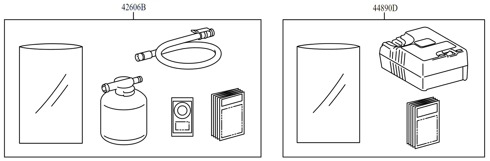
<p>The Toyota Corolla Cross Hybrid (CCH) does not include a spare wheel and jack assembly. This hybrid model comes with a Tire Puncture Repair Kit consisting of a tire sealant part <strong># 42606B</strong> and air compressor <strong># 44890D</strong> in lieu of the spare wheel and jack.</p>

<p><img src="/wp-content/uploads/2024/05/toyota-corolla-cross-hybrid-tire-kit.webp" alt="corolla cross hybrid tire kit" /></p>

<p>The lack of spare wheel in the Corolla Cross Hybrid is often not disclosed at purchase time. Most drivers assume that a spare is included — only to <a href="https://www.corollacrossforum.com/search/13063/?q=spare+tire&amp;o=relevance">discover</a> the missing <a href="https://www.reddit.com/r/CorollaCross/search/?q=spare+tire">spare</a> later.</p>

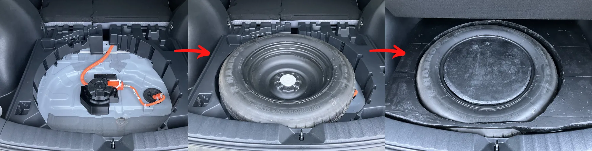
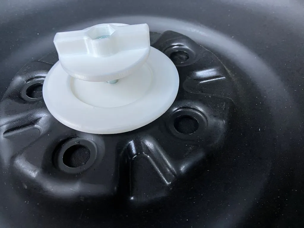
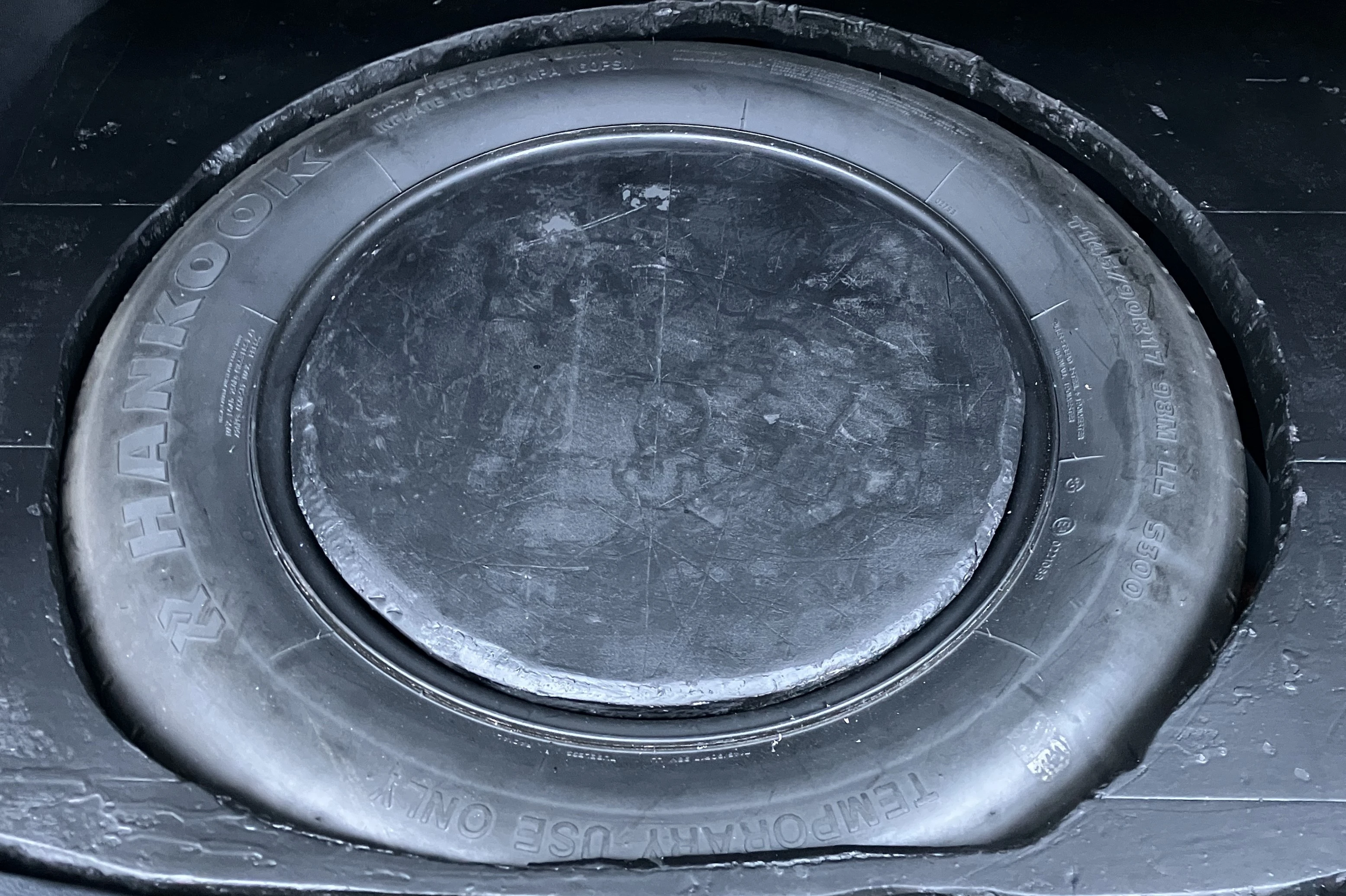
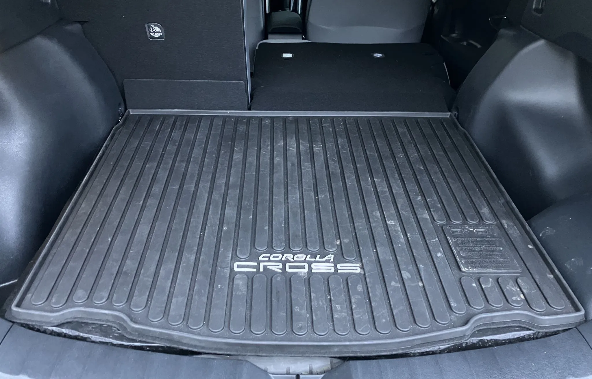
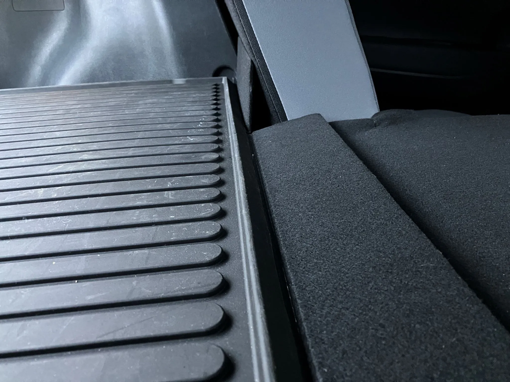
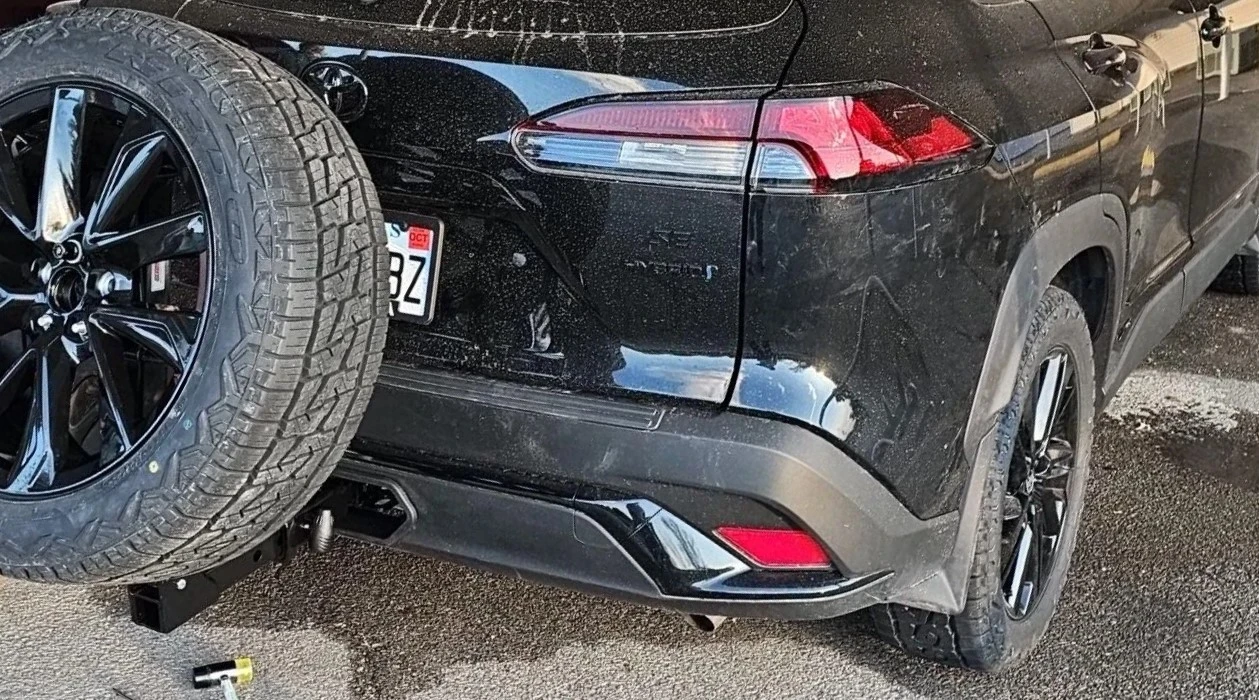
<p>Despite the lack of spare wheel shipped with the car, it IS possible to fit a spare wheel and jack under the cargo area of the hybrid model with smart positioning and spacers.</p>

<p><img src="/wp-content/uploads/2024/05/toyota-corolla-cross-spare-tire-mount-storage.webp" alt="corolla cross hybrid spare tire mount solution" /></p>

<p><strong><a href="#-rear-spare-wheel-well-tire-holder">⭐ Skip to my spare wheel storage solution for the Toyota Corolla Cross Hybrid</a></strong></p>

<video style="max-width:100%; height:auto;" width="768" height="432" autoplay="" loop="" muted="" playsinline="">
 <source src="/assets/images/store/spare-tire-mount-assembly-animation-tire-hold-down-spacer.webm" type="video/webm" />
 <source src="/assets/images/store/spare-tire-mount-assembly-animation-tire-hold-down-spacer.mp4" type="video/mp4" />
</video>

<p><a href="/store/">🛒 <em>Get the Toyota Corolla Cross Hybrid Spare Tire Mount</em></a></p>

<p>See spare tire mount <a href="/reference/toyota-corolla-cross-hybrid-spare-wheel-holder-directions/">assembly notes</a> and videos below.</p>

<iframe style="max-width:100%; height:auto;" width="800" height="450" src="https://www.youtube.com/embed/kHzdqbQ0Vwk?si=Gs0Eo5GvHKTzxLZn" title="YouTube video player" frameborder="0" allow="accelerometer; autoplay; clipboard-write; encrypted-media; gyroscope; picture-in-picture; web-share" referrerpolicy="strict-origin-when-cross-origin" allowfullscreen=""></iframe>

<iframe style="max-width:100%; height:auto;" width="800" height="450" src="https://www.youtube.com/embed/QlGANBVZVjA" title="YouTube video player" frameborder="0" allow="accelerometer; autoplay; clipboard-write; encrypted-media; gyroscope; picture-in-picture; web-share" referrerpolicy="strict-origin-when-cross-origin" allowfullscreen=""></iframe>

<p>The manufacturer’s decision to not skip the spare wheel seems to be both a design and cost savings constraint.</p>

<ul>
  <li>

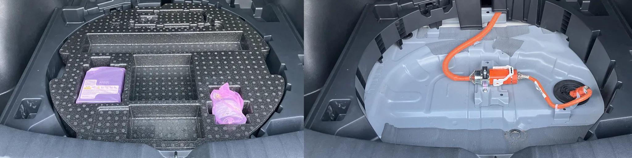
    <p>The hybrid system’s orange power cable is run through and exits the car body in the spare wheel well. This cable placement takes up vertical space in the wheel well and prevents most spare tires from fitting in there without crushing and rubbing the cable.</p>
  </li>
  <li>
    <p>A tire puncture repair kit is significantly lighter and cheaper for the manufacturer to include in the car than a larger spare wheel, scissor jack, jack handle, and tire wrench.</p>
  </li>
  <li>
    <p>Other Toyota hybrids include a spare wheel so the omission of spare in the Corolla Cross Hybrid is unlikely to be safety related.</p>
  </li>
</ul>

<p><img src="/wp-content/uploads/2024/05/tire-puncture-repair-kit.webp" alt="Tire puncture repair kit" /></p>

<p>For most drivers the tire puncture repair kit is sufficient if they stay near the road and a tow truck can be called. You don’t even need to use the tire patch it. Just have the car towed to the tire shop and get a new/used tire mounted. Using the tire patching liquid may mess with the Tire Pressure Monitoring System (TPMS) sensor so you may need to have the TPMS sensor replaced if you use the tire patch kit. Additionally tire patch kit can only seal smaller punctures in the thread and not the sidewall so the patch kit is not a complete spare tire replacement.</p>

<p><img src="/wp-content/uploads/2024/05/spare-tire-kit.webp" alt="Spare tire repair kit" /></p>

<p>For the rest of us, a spare wheel may be useful due to lack of infrastructure, bad roads, or other reasons.</p>

<p>If you do end up getting a spare tire for your hybrid, you keep the bonus of having the tire puncture repair kit’s portable 12V air compressor w/ built in pressure indicator! The tire inflator that comes with the Corolla Cross Hybrid is an air compressor can be used to inflate tires without requiring use of the sealant fluid. The included compressor is useful for topping off your tires or airing up after going off road!</p>

<p>I have put all the info on the Corolla Cross Hybrid spare wheel in this post and continuously update the post as needed.</p>

<h3 id="tow-hook-eyelet">Tow Hook Eyelet</h3>

<p>There is no way to attach the standard <a href="https://autoparts.toyota.com/products/product/hook-assy-fr-5196016030">tow hook eyelet</a> part <strong># 5196016030</strong> to the Corolla Cross Hybrid.</p>

<p>Toyota skipped including a tow eyelet in the Corolla Cross Hybrid. Buying the Toyota tow eyelet for the hybrid model is no use, however. The hybrid should share a similar body to its gas sibling with small exterior differences such as the hybrid exclusive bumper cover design.</p>

<p>Confusingly, the hybrid vehicle manual mentions using the tow hook and there exist front and rear popout panels in a hybrid trim specific bumper but no threaded holes or solid metal for tow eyelet attachment behind the popouts.</p>

<h2 id="spare-rim-and-tire-size">Spare Rim and Tire Size</h2>

<dl>
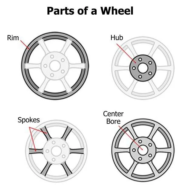
  <dt><img src="/wp-content/uploads/2024/05/parts-of-a-wheel-rim.webp" alt="parts of a wheel rim" /></dt>
  <dd><em>Source: <a href="https://www.researchgate.net/publication/372788696_CAD_Modelling_and_Fatigue_Analysis_of_a_Wheel_Rim_Incorporating_Finite_Element_Approach">CAD Modelling and Fatigue Analysis of a Wheel Rim Incorporating Finite Element Approach</a></em></dd>
</dl>

<p>Buying a wheel has 2 parts, the rim and tire. The rim is the inner metal circle that the outer rubber tire is mounted around. I refer to the wheel and tire interchangeably in the rest of this post since “spare wheel” is synonymous to “spare tire” for most readers.</p>

<p>A compatible spare needs to meet the requirements below:</p>

<ul>
  <li>
    <p>The rim bolt pattern must match the vehicle bolt pattern.</p>
  </li>
  <li>
    <p>The rim bolt thread size should match the existing thread size.</p>
  </li>
  <li>
    <p>The rim center bore/hub bore must be wider than or equal to the vehicle hub bore.</p>
  </li>
</ul>

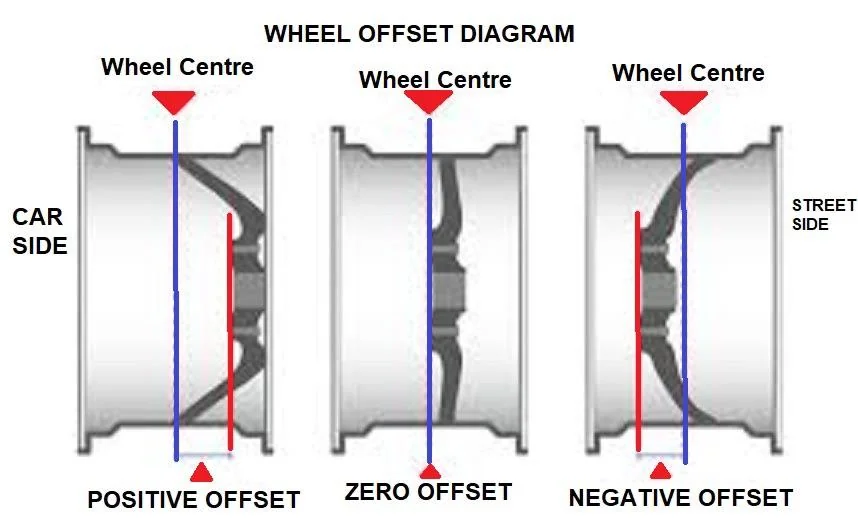
<p><img src="/wp-content/uploads/2024/05/wheel-offset-negative-vs-positive.webp" alt="wheel rim offset" /></p>

<ul>
  <li>
    <p>The rim offset (ET) should be within the vehicle’s compatible offset range.</p>
  </li>
  <li>
    <p>The diameter of the rim must clear the vehicle brake calipers. A rim diameter that is too small will cause the inner surface of the rim to impact the brake calipers.</p>
  </li>
</ul>

<blockquote>
  <p><em>A 17”/18” rim diameter fits best for the Corolla Cross. I tried fitting a donut spare with a 16” rim on my Corolla Cross Hybrid and there was about 1 cm of clearance to the brake calipers and the wheel spun freely so 16” rims with the right offset may work with a large enough tire sidewall height. Toyota’s official spare tire rim for the Corolla Cross is 17”.</em></p>
</blockquote>

<p><img src="/wp-content/uploads/2024/05/car-turning-diameters.webp" alt="car turning different diameters" /></p>

<ul>
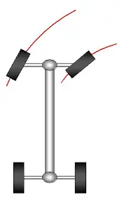
  <li>The outer diameter of wheel should match the outer diameter of the other wheels on the car as closely as possible. This outer diameter is the diameter of the rubber tire and not the diameter of the rim. A larger rim diameter does not necessarily equate to a larger wheel diameter since the tire may have a lower sidewall height. Too large of a diameter will cause the wheel to rub against the wheel well when the wheel turns. A mismatched diameter will cause extra wear on a differential connecting the wheels as one wheel will continuously rotate at a different speed. Wheels do not always turn at the same speed in normal driving when the car is turning and the outer wheel rotates faster so some variation in diameter is tolerable for short driving distances. Mismatched wheel diameters will have similar wear on the conponents as the car constantly turning in a tight circle.</li>
</ul>

<blockquote>
  <p><em>Matching wheel diameters is most important for the driven wheels. If the mismatched wheel is on an axle that does not have power (e.g. the rear wheels on a FWD vehicle), matching diameters is less important for the non-driven axel.</em></p>
</blockquote>

<ul>
  <li>The tire’s inner diameter must be designed to fit the rim diameter.</li>
</ul>

<p>These requirements are ordered in my recommended steps for finding a compatible spare.</p>

<h4 id="stock-corolla-cross-wheel-sizes">Stock Corolla Cross Wheel Sizes</h4>

<table>
  <thead>
    <tr>
      <th>Specification</th>
      <th>Corolla Cross (Gas/Hybrid) (USA/Canada)</th>
    </tr>
  </thead>
  <tbody>
    <tr>
      <td>Bolt Pattern</td>
      <td>5x114.3mm</td>
    </tr>
    <tr>
      <td>Bolt Thread Size</td>
      <td>M12 x 1.5</td>
    </tr>
    <tr>
      <td>Center Bore</td>
      <td>60.1 mm</td>
    </tr>
    <tr>
      <td>Offset (ET)</td>
      <td>43-(45)-47 (17” rim) / 48-(50)-52 (18” rim)</td>
    </tr>
    <tr>
      <td>Tire rim diameter</td>
      <td>17” / 18”</td>
    </tr>
    <tr>
      <td>OEM tire</td>
      <td>215/60R17 / 225/50R18</td>
    </tr>
  </tbody>
</table>

<h3 id="tire-diameters-and-suggested-spare-tire-sizes">Tire Diameters and Suggested Spare Tire Sizes</h3>

<p><a href="https://en.wikipedia.org/wiki/Tire_code">Tire sidewall code</a> format is WIDTH(mm) / SIDEWALL-HEIGHT-as-percentage-of-WIDTH TYPE RIM(in)</p>

<table>
  <thead>
    <tr>
      <th>Tire Code</th>
      <th>Toyota OEM Spec</th>
      <th>Type</th>
      <th>Outer Diameter</th>
    </tr>
  </thead>
  <tbody>
    <tr>
      <td>215/65R17</td>
      <td>✓</td>
      <td>full</td>
      <td>28.00” (711.3 mm)</td>
    </tr>
    <tr>
      <td>225/55R18</td>
      <td>✓</td>
      <td>full</td>
      <td>27.74” (704.7 mm)</td>
    </tr>
    <tr>
      <td>165/80D17</td>
      <td>✓</td>
      <td>compact</td>
      <td>27.39” (695.8 mm)</td>
    </tr>
    <tr>
      <td>155/80D17</td>
      <td>✓</td>
      <td>compact</td>
      <td>26.76” (679.8 mm)</td>
    </tr>
    <tr>
      <td>155/90R17</td>
      <td> </td>
      <td>compact</td>
      <td>27.98” (710.8 mm)</td>
    </tr>
    <tr>
      <td>145/90R17</td>
      <td> </td>
      <td>compact</td>
      <td>27.28” (692.8 mm)</td>
    </tr>
  </tbody>
</table>

<p>If the mix of metric and imperial units in the tire code is confusing, <a href="https://www.reddit.com/r/explainlikeimfive/comments/wt2660/comment/il1owgz/?utm_source=share&amp;utm_medium=web3x&amp;utm_name=web3xcss&amp;utm_term=1&amp;utm_content=share_button">you are not alone</a>.</p>

<p>You can use a tire code calculator such as <a href="https://www.tacomaworld.com/tirecalc">Tacoma World</a> to help calculate the wheel diameter.</p>

<h2 id="getting-the-corolla-cross-hybrid-spare-wheel-and-jack-set">Getting the Corolla Cross Hybrid Spare Wheel and Jack Set</h2>

<p>A spare wheel and jack set can be obtained from several sources that are somewhere in the range below:</p>

<ul>
  <li>
    <p><strong>Pay less -</strong> Put in the work and time to find a spare wheel and jack set.</p>
  </li>
  <li>
    <p><strong>Pay more -</strong> Buy a premade solution where someone has presumably done the homework and has an inventory of wheels and jacks to ship to you.</p>
  </li>
</ul>

<blockquote>
  <p>I got two compatible spare wheels: <strong>145/90R17</strong> and <strong>155/90D17</strong> from a 1st gen (2003) Ford Escape and 3rd gen (2009) CRV respectively at the scrapyard and a Toyota Corolla Cross jack assembly from an auto recycler.<br />
These two spare wheels are the closest diameter spare tire sizes to the stock Corolla Cross tire size that I have found. You can see that they are close to the OEM spare diameters in the <a href="#tire-diameters-and-suggested-spare-tire-sizes">tire code comparison chart</a> above.</p>
</blockquote>

<h3 id="compact-versus-full-size-spare">Compact versus Full Size Spare</h3>

<dl>
  <dt><img src="/wp-content/uploads/2024/05/compact-donut-spare-tire.webp" alt="compact donut spare" /></dt>
  <dd><em>Source: Mini Mania</em></dd>
</dl>

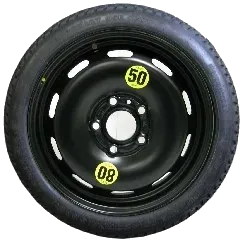
<p>Compact (aka donut) spares are relatively skinny with narrower tire widths and taller sidewall heights to compensate for a smaller diameter and width. These tires are usually lower cost and the rim is made of steel. Due to these compromises, compact spares are not designed to be driven on for long distances or high speeds. They are only made to get you back on the road and to the tire shop. Most tire shops do not mount tires on compact spare rims so it’s convenient to find a compact spare wheel mounted with the right tire size.</p>

<p><img src="/wp-content/uploads/2024/05/full-size-tire.webp" alt="full size wheel" /></p>

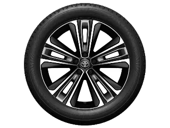
<p>Full size spares are the same size as the original rim and tire. A full size spare is basically the same rim and tire as the other wheels on the vehicle.</p>

<p>Getting a full size spare can be as simple as ordering the whole wheel from the manufacturer or dealer since it is the same wheel as the other wheels on the vehicle.</p>

<p>See <a href="#tire-diameters-and-suggested-spare-tire-sizes">Tire Diameters and Suggested Spare Tire Sizes</a> above for suggested wheel sizes.</p>

<h3 id="compatible-vehicles">Compatible Vehicles</h3>

<p>There are many other vehicles with a similar wheel size to the Corolla Cross. You can get a list of such vehicles with compatible wheels by searching all vehicles that have the same wheel size as the Corolla Cross on websites such as <a href="https://www.wheel-size.com/">Wheel-Size.com</a>.</p>

<p>I generated a partial list of CCH compatible vehicles that I printed out and brought to the scrapyard with me. Wheel-Size.com only allows me to search within a small offset range at a time so the full list of compatible vehicles is much greater. The partial list including 16” and 17” rims can be viewed <a href="/wp-content/uploads/2024/05/corolla-cross-compatible-vehicles.txt">here</a> and may be a starting point.</p>

<p>A 3D printed <a href="https://makerworld.com/en/models/493853">5x114.3mm bolt pattern and 60.1mm template</a> was useful to quickly check found tires’ bolt pattern and bore diameters at the scrapyard.</p>

<h3 id="compact-jack-assembly">Compact Jack Assembly</h3>

<p>Don’t forget to bring along a jack and lug nut wrench to actually lift the vehicle and swap in the spare wheel.</p>

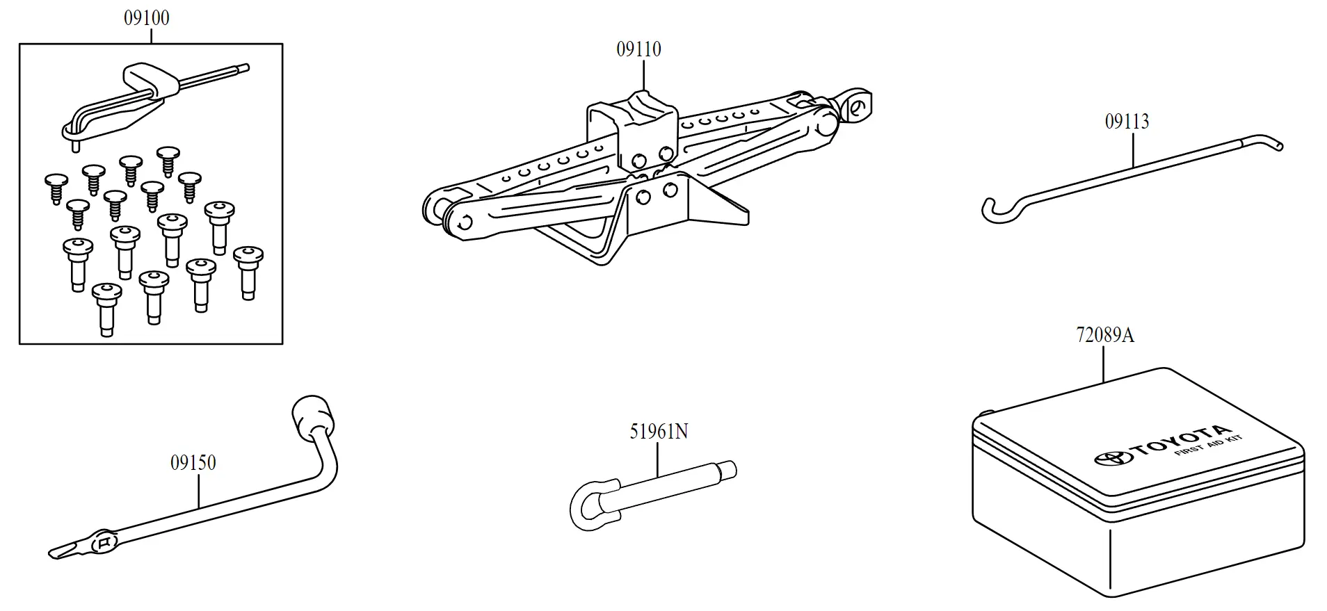
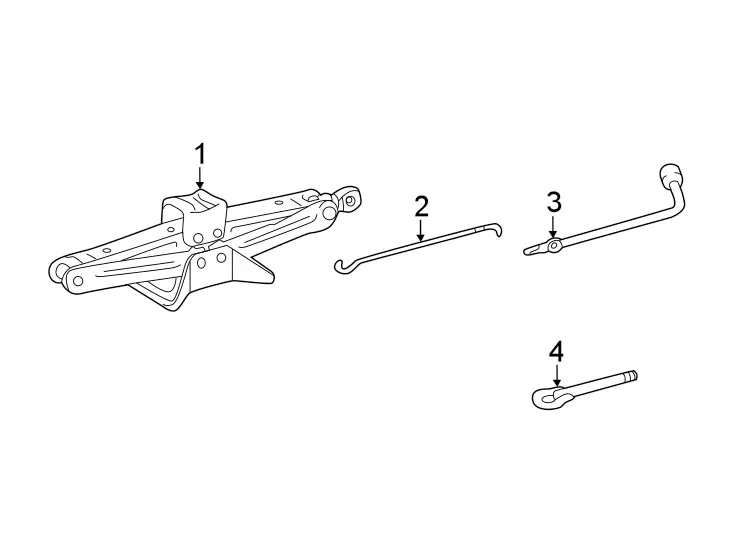
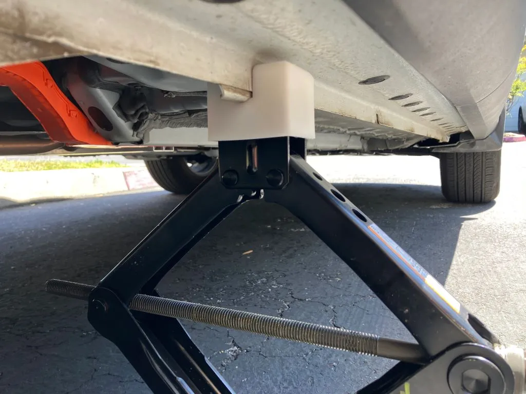
<p>Toyota’s included scissor jack in the gas Corolla Cross is designed to fit beneath the rear cargo floor. This jack and the jack storage compartment are especially small compared to common scissor jacks. All the jack set parts are under the <a href="https://parts.lakelandtoyota.com/showAssembly.aspx?ukey_assembly=2523591&amp;ukey_product=17083816">REAR BODY &amp; FLOOR. JACK &amp; COMPONENTS</a> kit.</p>

<p><img src="/wp-content/uploads/2024/05/toyota-corolla-cross-jack-assembly.webp" alt="toyota corolla cross jack assembly diagram" /></p>

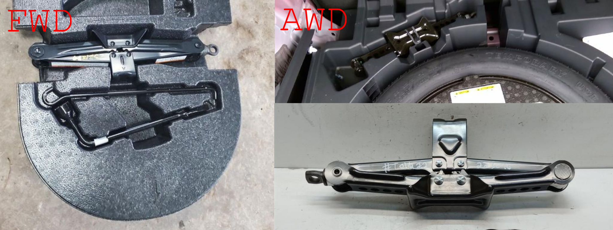
<p>The gas only Corolla Cross FWD and AWD models come with different jacks. Toyota has separate part numbers for these jacks.</p>

<p><strong>FWD jack part # 0911116060</strong></p>

<p><strong>AWD jack part # 091110A030</strong></p>

<p><img src="/wp-content/uploads/2024/05/cc-jack-fwd-awd.webp" alt="toyota corolla cross jack assembly fwd awd comparison" /></p>

<p>The FWD jack comes stored in an oval foam block that sits inside the spare wheel rim. It appears to have a weight capacity of 1100kg.</p>

<p>The AWD jack comes stored in the front/right slot in the plastic cargo floor deck. It appears to have a weight capacity of 1000kg.</p>

<p>The FWD jack can be identified by a lifting plate that is lower than the AWD lifting plate. The FWD jack has a oval stamp on the side while the AWD jack has a triangular stamp in the same position. AWD jack MSRP is about $5 higher.</p>

<p>I got the FWD jack and it was able to lift my Corolla Cross Hybrid to a sufficient height needed to lift the wheels off the ground.</p>

<p>The wheel lug wrench and jack handle parts are the same between the FWD and AWD models. These parts are held in the center foam block inside the spare tire on both models.</p>

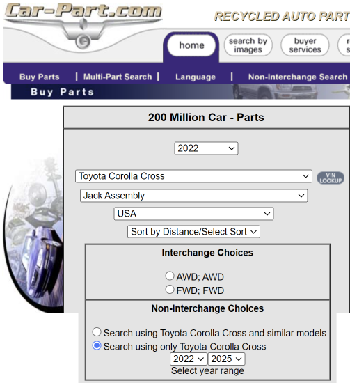
<p>The compact Corolla Cross jack assembly can be located at auto recyclers using <a href="https://www.car-part.com/">Car-Part.com</a> with the below search options.</p>

<p><img src="/wp-content/uploads/2024/05/car-part-com-jack-assembly.webp" alt="car-part.com toyota corolla cross jack assembly search" /></p>

<p>You can use a larger scissor jack to lift the car as well but it will not fit into the rear storage slot in the plastic cargo deck so you will need to store it in the spare wheel well or other part of the cargo area.</p>

<h3 id="sourcing-options">Sourcing Options</h3>

<p>These are listed below in acquiring a spare and jack set in the order of most work -&gt; highest cost.</p>

<p>I recommend sourcing in the following order:</p>

<ol>
  <li>Scrapyard</li>
  <li>Secondhand OEM</li>
  <li>Official Dealer</li>
  <li>Aftermarket</li>
</ol>

<p><strong>2025 Update:</strong> The verdict is in after long term feedback from customers. Toyota OEM spare (150/70R17), Value Spare, and other make/model OEM spares fit better due to the lower Flange Thickness of those rims.</p>

<h4 id="scrapyardpick-and-pull">Scrapyard/Pick and Pull</h4>

<p>The Toyota Corolla Cross is a relatively new vehicle and consequently, there are not many salvage Corolla Crosses to pull used parts from.</p>

<p><img src="/wp-content/uploads/2024/05/pick-n-pull.webp" alt="scrapyard aerial" /></p>

<p>Scrapyards usually have an online searchable listing of avaiable vehicles in their yards. These other vehicles may ride on similar tires to the Corolla Cross and a wheel compatibility can be determined as described in <a href="#compatible-vehicles">Compatible Vehicles</a>.</p>

<p>Spare wheels stored inside in trunk are easier to retrieve while spares mounted underneath the vehicle can be inaccessible if the scrapyard stacks the vehicle on welded rims.</p>

<p>Furthermore, scrapyards usually prohibit using jacks on premises for safety reasons and remove the scissor jacks from the cars in the yard. Still, they might forget to remove the jack so I’ve been able to find brand new scissor jacks several times.</p>

<p>I recommend searching online and visiting your local scrapyard at least once to see if you have any luck. You may be able to to get a new/barely used spare wheel for under $30 when it would otherwise cost 5-10x from an online seller!</p>

<h4 id="secondhand-oem">Secondhand OEM</h4>

<p>If someone is selling a Corolla Cross or compatible vehicle, you may be able to buy just the full size or compact wheel.</p>

<p>I did not have much luck finding a Corolla Cross OEM spare early 2024 since most sellers do not want to part out a new/driveable vehicle.</p>

<p>There are sellers online that pick out spare tires from salvage cars and sell the tires and jack assembly both individually and together. Search the spare tire size you are looking for on the marketplace site and confirm that the spare rim has the <a href="#stock-corolla-cross-wheel-sizes">correct bolt patterns size/spacing and center bore diameter</a>.</p>

<p>There is no foolproof metbhod to verify if the spare rim offset will fit the Corolla Cross Hybrid. Comparing the original vehicle for the spare wheel and the Corolla Cross Hybrid’s OEM wheel offsets <em>should</em> be sufficient. I have not seen a 17” spare rim with matching bolt specs and center bore not fit the Corolla Cross Hybrid yet.</p>

<ul>
  <li>
    <p><a href="https://www.ebay.com/sch/i.html?_from=R40&amp;_nkw=toyota+corolla+cross+spare+tire&amp;_sacat=0">Ebay vendors - “toyota corolla cross spare tire”</a></p>
  </li>
  <li>
    <p><a href="https://www.ebay.com/sch/i.html?_from=R40&amp;_nkw=145%2F90r17+escape&amp;_sacat=0&amp;_odkw=145%2F90r17&amp;_osacat=0">Ebay vendors - “145/90R17 escape”</a>*</p>
  </li>
</ul>

<h6 id="i-use-a-14590r17-spare-tire-from-a-01-04-ford-escape-as-the-spare-in-my-corolla-cross-hybrid"><em>*I use a 145/90R17 spare tire from a 01-04 Ford Escape as the spare in my Corolla Cross Hybrid.</em></h6>

<h4 id="aftermarket">Aftermarket</h4>

<p>There are several turnkey third party spare wheel solutions but these vendors do not sell a perfect matching wheel size for the Corolla Cross. They usually have an selection of tire sizes for multiple cars and will usually ship you a compatible 17” or 18” rim with a tire that they consider “close enough” to the Corolla Cross wheel diameter.</p>

<blockquote>
  <p>⚠️ Some aftermarket vendors’ special alloy rims sit very high on the CCH spare tire upgrade kit due to rim designs with high offsets. This may raise the cargo floor significantly and require an extra-thick spacer or other workarounds!<br />
I recommend getting a <strong>compatible steel compact donut spare rim style</strong> (usually painted black) described <a href="#compact-versus-full-size-spare">above</a> through the scrapyard or Ebay method.</p>
</blockquote>

<p>Aftermarket vendors that offer Corolla Cross spares (no endorsement provided):</p>

<ul>
  <li>
    <p><a href="https://valuespare.com/product/2023-2024-corolla-cross-spare-tire/?aff=2">Value Spare</a>* - <a href="https://amzn.to/3XY4V8T">Amazon</a>*</p>
  </li>
  <li>
    <p><a href="https://amzn.to/3zCzIi3">Amazon vendors</a>*</p>
  </li>
  <li>
    <p><a href="https://modernspare.com/product/2023-2024-toyota-corolla-cross-spare-tire-kit-options/">Modern Spare</a> - <a href="https://amzn.to/3zFMFYt">Amazon</a>*</p>
  </li>
  <li>
    <p><a href="https://ez-sparewheel.com/products/18-alloy-spare-wheel-and-tire?vehicle=2023%20Toyota%20Corolla%20Cross%20(2.0i%20Hybrid)">EZ Spare Wheel</a></p>
  </li>
</ul>

<h6 id="affiliate-link"><em>*affiliate link</em></h6>

<p>These vendors also sell scissor jacks and wheel covers. These scissor jacks may be white labeled versions of mass produced jacks from China sold on Amazon and other sites if you shop around. Most third party jacks will NOT fit in the plastic storage slot built into the car.</p>

<p>A wheel cover is not needed if you store the tire in the spare wheel well underneath the cargo deck floor as described further down.</p>

<h4 id="official-dealer">Official Dealer</h4>

<p>This is the most expensive solution but also a manufacturer guaranteed compatible solution that is covered by warranty.</p>

<p>The Toyota Corolla Cross Temporary Spare Wheel is part <a href="https://autoparts.toyota.com/products/product/wheel-temporary-spa-4261b0r010">#4261B-0R010</a>. 17x4 should be the correct rim size. This part only includes the rim and not the stock <strong>165/80D17</strong> or <strong>155/80D17</strong> spare tire that goes around the rim. This rim fits the hybrid model as well.</p>

<dl>
  <dt><img src="/wp-content/uploads/2024/05/original-corolla-cross-spare-trunk-clearance.webp" alt="original corolla cross spare tire trunk height clearance" /></dt>
  <dd><em>Source: <a href="https://www.corollacrossforum.com/posts/5610/">treehouse34</a></em></dd>
</dl>

<p>A driver tried fitting the original Corolla Cross spare into the hybrid model but the OEM spare <a href="https://www.corollacrossforum.com/posts/5610/">does not fit flush in the spare wheel well</a> due to the power cable disconnect lever.</p>

<h2 id="corolla-cross-hybrid-spare-wheel-storage">Corolla Cross Hybrid Spare Wheel Storage</h2>

<p>Now that you found a spare wheel for your Toyota Corolla Cross Hybrid, there are a couple of choices for storing the spare and jack.</p>

<h3 id="trunkcargo-platform">Trunk/Cargo Platform</h3>

<p>Leave the spare wheel and jack on top of the cargo platform like any other luggage.</p>

<p><img src="/wp-content/uploads/2024/05/strap-spare-in-trunk.webp" alt="strap spare tire in trunk" /></p>

<p>Tossing the parts in the back is a quick and easy storage solution but has some drawbacks. The spare wheel and jack will take up volume in the cargo area that could be used for other items. If not tied down, the spare wheel and jack will slide around the cargo area during driving and could go flying in a collision.</p>

<h3 id="rear-spare-wheel-well">Rear Spare Wheel Well</h3>

<p>Spare wheels stored inside the car are often placed in the rear spare wheel well which is the circular depression underneath  the rear cargo/truck floor.</p>

<p>This spare wheel well can be found in the Toyota Corolla Cross. If you lift up the plastic cargo platform, there is a large black foam block with cutouts holding the included tire patch and inflator kit. This foam piece sits in between two hard plastic cargo decks pieces on both sides of the body. In the gas only model of the Corolla Cross, this foam block rests inside the spare wheel. You can remove this foam piece to reveal the spare wheel well.</p>

<p>The Corolla Cross Hybrid has an orange power cable routed through this area. The power cable emerges from underneath the rear middle passenger seat, runs to an orange and white high voltage power disconnect switch bolted to the center of the floor, and exits through a rubber lined hole in floor on the right.</p>

<p>Without special positioning, this power cable arrangement in the rear area prevents easy storage of a spare due to the need to avoid repeated stress and moving of the power cable.</p>

<p><strong>The ideal spare tire solution should:</strong></p>

<ol>
  <li>Hold the spare tire in place without resting on or rubbing the power cable.</li>
  <li>The top surface of the spare tire should be close to the top surface of the cargo deck pieces so the cargo platform can be laid flat with the weight evenly distributed between the sides and center.</li>
  <li>The power disconnect switch should remain usable for easy access if needed.</li>
  <li>Prevent the spare tire from moving about during normal driving.</li>
</ol>

<h3 id="-rear-spare-wheel-well-tire-holder">⭐ Rear Spare Wheel Well Tire Holder</h3>

<p><img src="/wp-content/uploads/2024/05/toyota-corolla-cross-spare-tire-mount-assembly-animated.webp" alt="spare tire mount animated assembly" /></p>

<p>I designed a spare wheel mount that fits over power disconnect switch and is secured using existing brackets. The mount raises the spare wheel above the power cables and raises the trunk floor height to be level with the folded rear passenger seats.</p>

<p>This Toyota Corolla Cross Hybrid spare wheel mount is available on my <a href="/store/">Store</a>.</p>

<p><a href="/store/">🛒 <em>Get the Toyota Corolla Cross Hybrid Spare Tire Mount</em></a></p>

<h4 id="no-drilling">No Drilling</h4>

<p><img src="/wp-content/uploads/2024/05/spare-tire-mount-bolt-points.webp" alt="spare tire mount bolt points" /></p>

<p>The mount bolts to existing unused holes on the metal bracket underneath the high voltage cable disconnect lever. The setup can be fastened with a normal hex bolt driver.</p>

<h4 id="high-voltage-power-cable-clearance">High Voltage Power Cable Clearance</h4>

<p>The holder raises the spare wheel above the power cable runs so that the spare does not rub the cable.</p>

<p><img src="/wp-content/uploads/2024/05/spare-tire-sitting-on-holder.webp" alt="spare tire sitting on holder" /></p>

<p>The spare rests on the holder on a level plane with the left and right plastic cargo deck pieces. The cargo deck/trunk floor actually slopes rearward and is not at 0° relative to the cabin floor.</p>

<p><img src="/wp-content/uploads/2024/05/spare-tire-holder-cable-connector-lever-action.webp" alt="spare tire power cable disconnect lever action" /></p>

<p>This tire holder allows the power disconnect switch to be accessed without needing to remove the holder.</p>

<dl>
  <dt><img src="/wp-content/uploads/2024/05/3d-printed-tire-hold-down-bolt.webp" alt="3d printed spare tire hold down bolt" /></dt>
  <dd><em>Spare Tire Hold Down Bolt - <a href="https://makerworld.com/en/models/443704">Download and 3D print it</a></em></dd>
</dl>

<p>The spare tire can be held in place by any compatible tire hold down with a long enough bolt. I designed a 3D printable <a href="https://makerworld.com/en/models/443704">tire hold down</a> that uses the standard M8 bolt diameter present on most vehicles.</p>

<h4 id="cargo-deck-height-adjustment">Cargo Deck Height Adjustment</h4>

<p>Depending on the width of your spare tire and the offset of the rim, the top surface of the tire may sit above the top of the left and right plastic cargo decks. The foldable cargo platform needs a flat surface to sit on. This height difference be remedied by raising the cargo decks from above or below to be the same height as the spare tire.</p>

<blockquote>
  <p>The wider the spare tire width (this is the first number in the tire code), the higher your spare tire will rest. It is a balancing act to find a narrow enough spare tire with a high sidewall ratio to match the full size Corolla Cross wheel diameter. Good tire size matches and donor vehicles are listed in the section above.</p>
</blockquote>

<dl>
  <dt><img src="/wp-content/uploads/2024/05/corolla-cross-spare-tire-cargo-deck-riser-bottom.webp" alt="cargo deck riser from below" /></dt>
  <dd><em>Toyota Cargo Deck Bottom Riser - <a href="https://www.printables.com/model/1694896-toyota-corolla-cross-cargo-deck-bottom-riser">Download and 3D print</a></em></dd>
</dl>

<p>My initial attempt was designing risers to fit underneath the left and right cargo decks’ feet. While the risers fit fine underneath the cargo decks, the cargo deck was quite wobbly.</p>

<p>A Corolla Cross Hybrid owner <a href="https://www.reddit.com/r/CorollaCross/comments/1693rxf/comment/jz0mn9v/?utm_source=share&amp;utm_medium=web3x&amp;utm_name=web3xcss&amp;utm_term=1&amp;utm_content=share_button">wrote</a> that he was able to use <a href="https://imgur.com/a/605t3fG">cut 3” wood spacers</a> to elevate a CRV spare wheel above the orange power cables.</p>

<h4 id="cargo-deck-riser">Cargo Deck Riser</h4>

<p>I had better luck creating a spacer riser between the cargo decks and the cargo floor platform. My 145/90R17 compact spare mounted on my tire holder was ~1.5” higher than the cargo decks.</p>

<h5 id="rigid-riser-my-new-method-in-2025">Rigid Riser (My new method in 2025)</h5>

<p><img src="/wp-content/uploads/2025/01/cargo-spacer-header.webp" alt="cargo deck plastic riser" /></p>

<p>The <a href="/store/toyota-corolla-cross-hybrid-spare-wheel-cargo-riser/">rigid cargo riser</a> provides a stable flat surface for the cargo floor by lifting the existing cargo deck to be level with the spare tire. This kit of interlocking parts easily assembles to cover the entire cargo deck area minus the spare tire hole.</p>

<p><img src="/wp-content/uploads/2025/01/cargo-spacer-quad.webp" alt="cargo deck plastic riser quad" /></p>

<p>The riser incorporates raised edges on the left and right side and a center positioning hole to keep the cargo floor from shifting just like the stock cargo setup that the riser elevates.</p>

<p>The “rise height” is customizable and the riser can be made without a spare tire hole if desired. The riser can be created on any 3D printer or CNC machine with at least a 256x256 workspace.</p>

<p><strong>The rigid riser is a replacement of my initial foam riser attempt below after lessons learned over a year of carrying cargo and overlanding.</strong> It has improved durability, fitment, and cargo floor retention.</p>

<h5 id="foam-riser-my-old-method-in-2024">Foam Riser (My old method in 2024)</h5>

<blockquote>
  <p><a href="https://en.wikipedia.org/wiki/Polystyrene#Extruded_polystyrene_(XPS)">Extruded foam</a> is preferred to expanded foam. It is much denser, stronger, and easier to cut with less mess.</p>
</blockquote>

<p>I cut a 1.5” thick board of extruded foam from the hardware store to fit on top of the left and right cargo decks and around the spare tire. Extruded foam can be cut with a retractable utility knife or hot knife. I used a utility knife for this attempt with acceptable results.</p>

<p><img src="/wp-content/uploads/2024/05/corolla-cross-spare-tire-cargo-deck-riser-spacer.webp" alt="corolla cross hybrid spare tire cargo deck riser spacer foam" /></p>

<p>I cut a small circle in the top of the foam where the cargo platform’s bottom circular protrusion sticks out so that the platform does not slide around. Later on, I 3D printed a <a href="https://www.printables.com/model/1022154-toyota-cargo-deck-hole-buffer-holder">cargo deck circle buffer</a> out of flexible TPU to absorb some of the shifting movement of the cargo deck and distribute the force over a larger area to decrease wear and tear of the foam.</p>

<p><img src="/wp-content/uploads/2024/05/cargo-deck-circle-buffer.webp" alt="corolla cross hybrid spare tire tpu buffer" /></p>

<p><img src="/wp-content/uploads/2024/05/corolla-cross-spare-tire-foam-insert.webp" alt="corolla cross hybrid spare tire foam insert" /></p>

<p>I trimmed a piece of the foam to sit above the inside of the spare rim similar to the foam blocks that come in the gas model. These two pieces of foam support the foldeable cargo platform along the side and center.</p>

<p>After cutting, I sealed the foam with wood PVA glue and spray painted it black.</p>

<p>Extruded foam is still soft foam in the end - I saw some wear and tear on the foam as I moved the tire and cargo components around during my design and refinement. The pink extruded foam board I got was also pre-perforated at 1 ft increments which made it less strong than a solid board.</p>

<blockquote>
  <p><del>If I needed to make the riser again, I would opt to use a more durable material combination such as a MDF/plywood + extruded foam sandwich. Shaping the harder material would be easier with a router or saw.</del>
I have fixed the durability and fitment issues of the foam spacer with the new <a href="#cargo-deck-riser">rigid spacer</a>.</p>
</blockquote>

<p><img src="/wp-content/uploads/2024/05/corolla-cross-all-weather-trunk-liner-mat.webp" alt="corolla cross hybrid cargo with mat" /></p>

<p>After placing the foam pieces on the cargo deck and in the spare wheel, the folding cargo platform can be laid on top to finish setting up the cargo area.</p>

<p><img src="/wp-content/uploads/2024/05/corolla-cross-hybrid-cargo-rear-seat-flat.webp" alt="corolla cross hybrid rear cargo passenger floor flat" /></p>

<p>The Corolla Cross Hybrid cargo floor is originally much lower than the backs of the folded rear passenger seats. The 1-1.5” rise in the the cargo platform height after the spacer makes the cargo floor level with the folded rear passenger seats which is nice for camping and transporting larger flat objects in the back.</p>

<h4 id="cargo-deck-spacer-dimensions">Cargo Deck Spacer Dimensions</h4>

<p><img src="/wp-content/uploads/2024/05/cch-cargo-spacer-top.webp" alt="cch cargo spacer dimensions top" /></p>

<p><img src="/wp-content/uploads/2024/05/cch-cargo-spacer-side.webp" alt="cch cargo spacer dimensions side" /></p>

<h3 id="spare-tire-hitch-mount">Spare Tire Hitch Mount</h3>

<p>The spare wheel could be mounted behind the car with a spare tire hitch mount that fits in the rear hitch receiver.</p>

<dl>
  <dt><img src="/wp-content/uploads/2024/05/spare-tire-hitch-mount.webp" alt="corolla cross hybrid spare tire hitch mount" /></dt>
  <dd><em>Source: <a href="https://www.reddit.com/r/CorollaCross/comments/1bpkpn0/spare_tire_thoughts/">Reddit</a></em></dd>
</dl>

<p>This gives a semi “Jeep Wrangler” looking setup except the spare tire hangs a few inches away from the liftgate rather than mounted directly to the car body like an actual Wrangler. This way, a full size spare wheel can be stored behind the vehicle without sacrificing any internal space.</p>

<blockquote>
  <p>The spare wheel well in the Corolla Cross is usually filled with foam and unused space so it can be made useful to store a compact spare wheel in the Rear Spare Wheel Well method.</p>
</blockquote>

<p>The major limitation with the hitch tire holder is that the hitch must be removed if access to the liftgate and trunk are needed unless a more expensive hitch tire holder with swing away function is used.</p>

<p><strong>Other limitations of a hitch mounted tire holder:</strong></p>

<ul>
  <li>
    <p>The vehicle license plate must be relocated to a visible location if the plate is blocked by the spare tire.</p>
  </li>
  <li>
    <p>The entire hitch tire holder or spare tire can be stolen if not locked with a locking hitch and locking lug nuts.</p>
  </li>
  <li>
    <p>Longer vehicle length, decreased departure angle, and center of gravity moved aft.</p>
  </li>
  <li>
    <p>Hitch tire holder may wobble when driving and turning.</p>
  </li>
  <li>
    <p>Increased tire degradation from UV damage unless the tire is protected with a cover.</p>
  </li>
</ul>

<p><em>The above limitations are also advantages of storing the spare tire inside the vehicle.</em> 😎</p>

<h3 id="vehicle-rooftop">Vehicle Rooftop</h3>

<p>Not recommended on most vehicles for reasons that can be found elsewhere. If you store the spare tire on the vehicle roof, I hope you secure it properly to prevent it from sliding off and hitting pedestrians and other vehicles.</p>

<h3 id="garage">Garage</h3>

<p>If storing the spare in the car doesn’t work, you could keep the spare in your garage or home. It’s helpful if a tire loses air overnight from a small puncture but you lose convenient access to the spare when away from home.</p>

<h2 id="corolla-cross-hybrid-accessories-storage">Corolla Cross Hybrid Accessories Storage</h2>

<p><img src="/wp-content/uploads/2024/05/oem-corolla-cross-jack-storage.webp" alt="oem cc hybrid jack storage" /></p>

<p>The scissor jack that comes with the other gas/FWD Corolla Cross models fits in the upper left plastic storage slot in the cargo deck. The rubber loop can be hooked across the slot to secure the jack. See <a href="#compact-jack-assembly">Compact Jack Assembly</a> for more jack details.</p>

<dl>
  <dt><img src="/wp-content/uploads/2024/05/tire-puncture-kit-holder.webp" alt="toyota corolla cross hybrid tire puncture kit holder and mount" /></dt>
  <dd><em>Toyota Tire Puncture Kit Holder and Mount in TPU- <a href="https://www.printables.com/model/1694892-toyota-tire-puncture-kit-holder-mount">3D print</a></em></dd>
</dl>

<p>If you made the right choice and put the spare wheel in the wheel well underneath the cargo floor, the original large foam block that previously held the Tire Puncture Repair Kit is removed and you can stash the jack handle, tire wrench, tire sealant, and inflator next to the spare in the wheel well or spare rim with soft TPU holders that I designed to prevent rattling.</p>

<dl>
  <dt><img src="/wp-content/uploads/2024/05/tire-wrench-jack-handle-cover-display.webp" alt="tire wrench and jack handle cover" /></dt>
  <dd><em>Toyota Tire Puncture Kit Holder and Mount in TPU- <a href="https://www.printables.com/model/918872-toyota-tire-wrench-and-jack-handle-cover-holder">3D print</a></em></dd>
</dl>

<p><img src="/wp-content/uploads/2024/05/tire-wrench-jack-handle-cover.webp" alt="tire wrench and jack handle storage" /></p>

<p>The original large foam block with cutouts can be stored at home or in the garage for future use. I haven’t figured out what the storage slots in the right side of the cargo deck were made to fit.</p>

<h2 id="actually-changing-the-tire">Actually Changing the Tire</h2>

<p>The most important part of swapping the spare tire is staying safe.</p>

<blockquote>
  <p>⛽ Check the pressure of your spare tire and inflate it to the listed pressure on the tire before storage and usage.</p>
</blockquote>

<dl>
  <dt><img src="/wp-content/uploads/2024/05/toyota-corolla-cross-jack-pad.webp" alt="toyota corolla cross jack pad" /></dt>
  <dd><em>Toyota Corolla Cross Jack Pinch Weld Pad in TPU - <a href="https://www.printables.com/model/883231-toyota-compact-scissor-jack-pinch-weld-pad">3D print</a></em></dd>
</dl>

<ol>
  <li>
    <p>Loosen the tire lug nuts with the socket wrench BEFORE lifting the car with the jack. If you loosen the lug nuts when the car is lifted in the air, the force used to loosen the nuts will transfer to the car and may cause the car to slip and fall off the lifting jack.</p>
  </li>
  <li>
    <p>Lift the car by the jacking points. If you use a scissor jack, position the jack perpendicular to the side of the car frame and lift the jack so that the lifting plate is centered on the reinforced pinch weld (where the pinch weld is folded over itself). If you use a floor jack, you can lift both sides of the car at once by lifting the centers points of the car frame marked by a raised divot to help with centering the floor jack lifting point. These points are described in the Corolla Cross Hybrid manual, but they are hard to find the first time until you realize that they are identified by round quarter sized divots.</p>
  </li>
  <li>
    <p>Remove the lug nuts</p>
  </li>
  <li>
    <p>Remove the original tire</p>
  </li>
  <li>
    <p>Put the spare tire on the bolts</p>
  </li>
  <li>
    <p>Finger tighten the lug nuts</p>
  </li>
  <li>
    <p>Lower the jack</p>
  </li>
  <li>
    <p>Tighten the lug nuts with the socket wrench AFTER lowering the car to the ground.</p>
  </li>
  <li>
    <p>Put the original tire in the trunk</p>
  </li>
</ol>

<h2 id="conclusion">Conclusion</h2>

<p>I tried to touch on all parts of the spare tire acquisition and mounting process in this post. Decrease the chance of being stranded on the side of the road or trail by pairing your Toyota Corolla Cross Hybrid with a spare tire and mount.</p>

<p><a href="/store/">🛒 <em>Get the Toyota Corolla Cross Hybrid Spare Tire Mount</em></a></p>

<h3 id="more-toyota-corolla-cross-hybrid-specs">More Toyota Corolla Cross Hybrid Specs</h3>

<p>There is some conflicting information on the internet on common parts for the North America CCH AWD 1st gen (2.0L 4 cylinder engine). The correct OEM part numbers are below:</p>

<table>
  <thead>
    <tr>
      <th>Part</th>
      <th>OEM Part No.</th>
      <th>Notes</th>
    </tr>
  </thead>
  <tbody>
    <tr>
      <td>Engine Air Filter</td>
      <td>17801-F2060</td>
      <td>This filter is almost a square shape and is NOT interchangeable with the filter for the gas Corolla Cross.</td>
    </tr>
    <tr>
      <td>Cabin Air Filter</td>
      <td>87139-YZZ83</td>
      <td> </td>
    </tr>
  </tbody>
</table>

<h3 id="supporting-more-of-my-designs">Supporting More Of My Designs</h3>

<p>3D printed objects that I design including those seen in this post are viewable on my <a href="/portfolio/">Portfolio</a>. I make designs to fill functional gaps in real life and I personally use all of my designs.</p>

<p>Most of my designs available for free on <a href="https://www.printables.com/@ansonl/">Printables</a> and <del><a href="https://makerworld.com/en/@ansonl">MakerWorld</a></del>. You can download and print them on your own 3D printer.</p>

<p>Physical versions of my designs are available for purchase from Anson Innovations LLC <a href="/store/">Store</a>. Get the good stuff straight from the source 📍!</p>

<h3 id="other-toyota-corolla-cross-accessories-that-may-interest-you">Other Toyota Corolla Cross accessories that may interest you</h3>

<h4 id="toyota-corolla-cross-integrated-windshield-mount">Toyota Corolla Cross Integrated Windshield Mount</h4>

<p><img src="/assets/images/store/toyota-safety-sense-3-integrated-dashcam-mount.webp" alt="toyota safety sense 3 integrated dashcam mount" /></p>

<p>This modular mount fits all new 2022+ Toyota vehicles [including the Corolla Cross] equipped with Toyota Safety Sense 3.0. Any accessory or dashcam with a GoPro style mount can be cleanly attached to your front windshield using this mount!</p>

<p><em><a href="https://www.printables.com/model/683181-2023-2024-toyota-integrated-front-windshield-mount">Download + 3D print - Integrated Dashcam Mount</a></em></p>

<p><em><a href="https://www.printables.com/model/729753-toyota-corolla-cross-hybrid-power-distribution-fus">Download + 3D print - Fuse Box Extended Height Cover</a></em></p>

<h4 id="toyota-corolla-cross-integrated-windshield-right-side-mount">Toyota Corolla Cross Integrated Windshield Right Side Mount</h4>

<p>A modular mounting point that clips into the right side of the front windshield bracket cover. I created this primarily hold a FasTrak toll road pass but any accessory or dashcam can be attached to the right side of the windshield with this mount.</p>

<p><em><a href="https://makerworld.com/en/models/494116">Download + 3D print - Fastrak Flex Transponder Mount</a></em></p>]]></content><author><name>Anson Liu</name></author><category term="auto" /><category term="toyota corolla cross" /><category term="corolla cross hybrid" /><category term="spare tire" /><category term="spare wheel" /><summary type="html"><![CDATA[Add a spare wheel and jack under the cargo area of your Toyota Corolla Cross Hybrid (CCH) as the overlanding gods intended. ![corolla cross hybrid tire kit](/wp-content/uploads/2024/05/toyota-corolla-cross-hybrid-tire-kit.webp) The hybrid AWD model of the Corolla Cross does not include a spare wheel or jack from the factory so we can add the spare ourselves. I made a tire mount that fits over the power cable lever and elevates the spare tire to avoid stressing the cable. [🛒 *Get the Toyota Corolla Cross Hybrid Spare Tire Mount*](/store/toyota-corolla-cross-hybrid-spare-wheel-holder/) Spare tire mount [assembly notes](/reference/toyota-corolla-cross-hybrid-spare-wheel-holder-directions/). ![corolla cross hybrid spare tire mount solution](/wp-content/uploads/2024/05/toyota-corolla-cross-spare-tire-mount-storage.webp) This post covers all things you need to find and mount a spare wheel in the Toyota Corolla Cross Hybrid AWD.]]></summary><media:thumbnail xmlns:media="http://search.yahoo.com/mrss/" url="https://ansonliu.com/wp-content/uploads/2024/05/toyota-corolla-cross-spare-tire-mount-storage.webp" /><media:content medium="image" url="https://ansonliu.com/wp-content/uploads/2024/05/toyota-corolla-cross-spare-tire-mount-storage.webp" xmlns:media="http://search.yahoo.com/mrss/" /></entry><entry><title type="html">Ultimaker S3/S5/S7 3D Printer PrusaSlicer Profile</title><link href="https://ansonliu.com/2024/04/ultimaker-s3-s5-s7-prusaslicer-profile/" rel="alternate" type="text/html" title="Ultimaker S3/S5/S7 3D Printer PrusaSlicer Profile" /><published>2024-04-15T00:00:00+00:00</published><updated>2024-04-15T00:00:00+00:00</updated><id>https://ansonliu.com/2024/04/ultimaker-s3-s5-s7-prusaslicer-profile</id><content type="html" xml:base="https://ansonliu.com/2024/04/ultimaker-s3-s5-s7-prusaslicer-profile/"><![CDATA[<p>Sometimes you just have to go off the rez (in a fun exploratory way).</p>

<p><a href="https://ultimaker.com/">Ultimaker</a> 3D printers usually print 3D files sliced using the <a href="https://github.com/Ultimaker/Cura">Ultimaker Cura</a> slicer software. Cura has more user exposed settings accessible through the GUI compared to <a href="https://slic3r.org/">Slic3r</a> forks such as <a href="https://github.com/prusa3d/PrusaSlicer">PrusaSlicer</a> and <a href="https://github.com/bambulab/BambuStudio">Bambu Studio</a>.</p>

<p>Cura can “repair” small non-manifold holes in 3D models and generate printer G-code that prints as the user intended. Cura is great for most use cases, but sometimes it fails to slice large, detailed dual object files that are already manifold.</p>

<blockquote>
  <p><strong>Manifold</strong> - A collection of points forming a certain kind of set, such as those of a topologically closed surface or an analog of this in three or more dimensions.</p>
</blockquote>

<p>In these rare cases, PrusaSlicer or Bambu Studio tend to have fewer slicing errors because they do not do 3D model repair (model repair in these slicers is provided through Microsoft 3D Builder). The drawback is that sliced non-manifold models in Slic3r forks look okay at first glance but have missing layers ands and features on closer inspection.</p>

<p>When generating detailed dual color map models, I can check for and fix nonmanifold errors with tools such as Blender. If Cura is unable to slice the manifold model, I may be able to slice it in PrusaSlicer. The newer Ultimaker S-line (S3/S5/S7) printers expect G-code in the default UFP format output by Cura which is compressed G-code with additional metadata. Luckily Ultimaker Cura and S-line printers can still output and process standard G-code with some caveats explained further down.</p>

<p><img src="/wp-content/uploads/2024/04/prusaslicer-ultimaker-printers.webp" alt="Prusaslicer profile supported ultimaker printers" /></p>

<h3 id="i-just-want-the-prusaslicer-profile">I Just Want The PrusaSlicer Profile!</h3>

<p>You just want to get the PrusaSlicer Ultimaker printer profiles and skip reading about the changes?</p>

<ol>
  <li>PrusaSlicer with a version ≥ 2.6.0 should automatically detect the new Ultimaker printer profiles when selecting new printer models.</li>
  <li>You can manually download the PrusaSlicer Ultimaker printer profiles from the PrusaSlicer-settings repo <a href="https://github.com/prusa3d/PrusaSlicer-settings/tree/master/live/Ultimaker">here</a>.</li>
</ol>

<h2 id="the-gcode-error">The Gcode “error”</h2>

<p>I’d like to print the model using the dual material Ultimaker S5/S7 3D printers at my work. As usual the PrusaSlicer generated G-code file is placed on a USB drive and loaded onto the Ultimaker printer.</p>

<p><img src="/wp-content/uploads/2024/04/ultimaker-print-file-list.webp" alt="ultimaker print file list" /></p>

<p>The G-code file is grayed out in the print file list on the printer with a red symbol next to it.</p>

<p><img src="/wp-content/uploads/2024/04/ultimaker-print-job-error.webp" alt="ultimaker print job error" /></p>

<p>The printer will refuse to print the G-code file when sliced and say that the file has an “error” with no other specific information.</p>

<h2 id="griffin-header">Griffin header</h2>

<p>G-code comes in multiple flavors because machine firmwares support different capabilities and commands. Most 3D printers support the standard Marlin G-code commands. Ultimaker created a new G-code flavor based on Marlin called <a href="https://community.ultimaker.com/topic/15555-inside-the-ultimaker-3-day-1-gcode/">Griffin</a> that has 2 main differences:</p>

<ol>
  <li>G-code header with print metadata</li>
</ol>

<div class="language-plaintext highlighter-rouge"><div class="highlight"><pre class="highlight"><code>;START_OF_HEADER
;HEADER_VERSION:0.1
;FLAVOR:Griffin
;GENERATOR.NAME:PrusaSlicer
;GENERATOR.VERSION:5.4.0
;GENERATOR.BUILD_DATE:{year}-{month}-{day}
;TARGET_MACHINE.NAME:Ultimaker S7
;EXTRUDER_TRAIN.0.INITIAL_TEMPERATURE:{first_layer_temperature[0]}
;EXTRUDER_TRAIN.0.MATERIAL.VOLUME_USED:{extruded_volume[0]}
;EXTRUDER_TRAIN.0.MATERIAL.GUID:0f12978a-8e3c-4147-b9ca-726d5ed59368
;EXTRUDER_TRAIN.0.NOZZLE.DIAMETER:{nozzle_diameter[0]}
;EXTRUDER_TRAIN.0.NOZZLE.NAME:AA {nozzle_diameter[0]}
;EXTRUDER_TRAIN.1.INITIAL_TEMPERATURE:{temperature[1] + standby_temperature_delta}
;EXTRUDER_TRAIN.1.MATERIAL.VOLUME_USED:{extruded_volume[1]}
;EXTRUDER_TRAIN.1.MATERIAL.GUID:0f12978a-8e3c-4147-b9ca-726d5ed59368
;EXTRUDER_TRAIN.1.NOZZLE.DIAMETER:{nozzle_diameter[0]}
;EXTRUDER_TRAIN.1.NOZZLE.NAME:AA {nozzle_diameter[0]}
;BUILD_PLATE.INITIAL_TEMPERATURE:[first_layer_bed_temperature]
;BUILD_VOLUME.TEMPERATURE:28
;PRINT.TIME:0
;PRINT.GROUPS:1
;PRINT.SIZE.MIN.X:{print_bed_min[0]}
;PRINT.SIZE.MIN.Y:{print_bed_min[1]}
;PRINT.SIZE.MIN.Z:0
;PRINT.SIZE.MAX.X:{print_bed_max[0]}
;PRINT.SIZE.MAX.Y:{print_bed_max[1]}
;PRINT.SIZE.MAX.Z:{max_print_height}
;SLICE_UUID:32daaf1d-f868-4a8e-ad06-8536b153e789
;END_OF_HEADER
</code></pre></div></div>

<ol>
  <li>Reduced G-code command set supported. Compared to standard Marlin G-code, the notables changes are:
    <ul>
      <li><code class="language-plaintext highlighter-rouge">G28</code>/<code class="language-plaintext highlighter-rouge">G29</code> homing and bed leveling replaced by <code class="language-plaintext highlighter-rouge">G280</code>.</li>
      <li><code class="language-plaintext highlighter-rouge">M82</code>/<code class="language-plaintext highlighter-rouge">M83</code> gone. Relative extrusion support removed.</li>
      <li><code class="language-plaintext highlighter-rouge">G2</code>/<code class="language-plaintext highlighter-rouge">G3</code> gone. No arc movement.</li>
    </ul>
  </li>
</ol>

<p><a href="https://community.ultimaker.com/topic/15555-inside-the-ultimaker-3-day-1-gcode/">Daid’s Ultimaker forum post</a> states that the below are the supported commands in the S-line printers.</p>

<div class="language-plaintext highlighter-rouge"><div class="highlight"><pre class="highlight"><code>G0, G1, G4, M104, M109, M140, M190, M106, M107, M201, M204, M205, M302, M400, M117
</code></pre></div></div>

<h2 id="creating-our-own-header">Creating our own header</h2>

<p>The Ultimaker S-line printer expects any G-code file to have the proper header as comments and movements to use absolute positioning. We can configure PrusaSlicer to autogenerate a valid header as part of the printer start G-code just like Cura.</p>

<p>If you want to see a valid header, you can slice a file in Cura and save a file as G-code format instead of UFP by changing the save file type to G-code when choosing the Save to Disk option.</p>

<h3 id="header-start">Header start</h3>

<div class="language-plaintext highlighter-rouge"><div class="highlight"><pre class="highlight"><code>;START_OF_HEADER
; Printer_Settings_ID: [printer_settings_id]
</code></pre></div></div>

<p>Starts the header. We add the PrusaSlicer <code class="language-plaintext highlighter-rouge">[printer_settings_id]</code> like other PrusaSlicer profiles’ start G-code for consistentcy.</p>

<h3 id="generator-info">Generator info</h3>

<div class="language-plaintext highlighter-rouge"><div class="highlight"><pre class="highlight"><code>;HEADER_VERSION:0.1
;FLAVOR:Griffin
;GENERATOR.NAME:PrusaSlicer
;GENERATOR.VERSION:5.4.0
;GENERATOR.BUILD_DATE:{year}-{month}-{day}
</code></pre></div></div>

<p>Slicer software information.</p>

<p>The Ultimaker S-line firmware uses the <code class="language-plaintext highlighter-rouge">GENERATOR.VERSION</code> field to compare against has a hard coded minimum version to warn about a lower Cura version. The provided version must have more than two decimal points if it consists only of numbers to avoid a <a href="/2024/03/ultimaker-gcode-footprint-halt/">crash due to being interpreted as an actual number</a>.</p>

<h3 id="target-machine-info">Target Machine info</h3>

<div class="language-plaintext highlighter-rouge"><div class="highlight"><pre class="highlight"><code>;TARGET_MACHINE.NAME:Ultimaker S7
</code></pre></div></div>

<p>I assume the Ultimaker printer could use this warn the user that the file was sliced for another printer model and possibly refuse to print it.</p>

<h3 id="temperature-and-extruder-information">Temperature and Extruder Information</h3>

<div class="language-plaintext highlighter-rouge"><div class="highlight"><pre class="highlight"><code>;EXTRUDER_TRAIN.0.INITIAL_TEMPERATURE:{first_layer_temperature[0]}
;EXTRUDER_TRAIN.0.MATERIAL.VOLUME_USED:{extruded_volume[0]}
;EXTRUDER_TRAIN.0.MATERIAL.GUID:0f12978a-8e3c-4147-b9ca-726d5ed59368
;EXTRUDER_TRAIN.0.NOZZLE.DIAMETER:{nozzle_diameter[0]}
;EXTRUDER_TRAIN.0.NOZZLE.NAME:AA {nozzle_diameter[0]}
;EXTRUDER_TRAIN.1.INITIAL_TEMPERATURE:{temperature[1] + standby_temperature_delta}
;EXTRUDER_TRAIN.1.MATERIAL.VOLUME_USED:{extruded_volume[1]}
;EXTRUDER_TRAIN.1.MATERIAL.GUID:0f12978a-8e3c-4147-b9ca-726d5ed59368
;EXTRUDER_TRAIN.1.NOZZLE.DIAMETER:{nozzle_diameter[0]}
;EXTRUDER_TRAIN.1.NOZZLE.NAME:AA {nozzle_diameter[0]}
;BUILD_PLATE.INITIAL_TEMPERATURE:[first_layer_bed_temperature]
;BUILD_VOLUME.TEMPERATURE:28
</code></pre></div></div>

<p>The <code class="language-plaintext highlighter-rouge">G280</code> command combines homing and bed leveling into a single command.</p>

<p>Homing a single or combination of axes in Marlin is done with <a href="https://marlinfw.org/docs/gcode/G028.html"><code class="language-plaintext highlighter-rouge">G28</code></a> and bed leveling is initiated with <a href="https://marlinfw.org/docs/gcode/G029.html"><code class="language-plaintext highlighter-rouge">G29</code></a>. It is up to the user to add additional G-code to preheat the bed and nozzles during the homing and bed leveling process.</p>

<p><code class="language-plaintext highlighter-rouge">G280</code> uses the header values for preheating the bed and nozzles during the homing and bed leveling procedure.</p>

<p>We fill these numbers in using PrusaSlicer’s feature to insert variables into G-code.</p>

<p>You can create your own material GUIDs by creating a custom material in Cura and copying the GUID from the generated G-code file. The header GUID is used to know if the official Ultimaker materials are used if the GUIDs match.</p>

<h3 id="printing-time-and-volume-info">Printing time and volume info</h3>

<div class="language-plaintext highlighter-rouge"><div class="highlight"><pre class="highlight"><code>;PRINT.TIME:0
;PRINT.GROUPS:1
;PRINT.SIZE.MIN.X:{print_bed_min[0]}
;PRINT.SIZE.MIN.Y:{print_bed_min[1]}
;PRINT.SIZE.MIN.Z:0
;PRINT.SIZE.MAX.X:{print_bed_max[0]}
;PRINT.SIZE.MAX.Y:{print_bed_max[1]}
;PRINT.SIZE.MAX.Z:{max_print_height}
</code></pre></div></div>

<p>Print volume information. This info is probably unused because <code class="language-plaintext highlighter-rouge">G280</code> <a href="/2024/03/ultimaker-gcode-footprint-halt/">dynamically calculates the print volume for adaptive bed leveling</a> using the points on the first and second layers.</p>

<h3 id="slice-uuid">Slice UUID</h3>

<div class="language-plaintext highlighter-rouge"><div class="highlight"><pre class="highlight"><code>;SLICE_UUID:32daaf1d-f868-4a8e-ad06-8536b153e789
</code></pre></div></div>

<p>A UUID to identify a sliced file. It’s not used so any UUID can be used.</p>

<h3 id="header-end">Header end</h3>

<div class="language-plaintext highlighter-rouge"><div class="highlight"><pre class="highlight"><code>;END_OF_HEADER
</code></pre></div></div>

<p>Signifies the end of the header.</p>

<h3 id="start-g-code">Start G-code</h3>

<p>What we normally consider start G-code will follow the header. This normally involves commands in the order:</p>

<ol>
  <li>Preheat and wait for bed to reach first layer temperature - <code class="language-plaintext highlighter-rouge">M140</code></li>
  <li>Preheat nozzles to standby temperature - <code class="language-plaintext highlighter-rouge">M109</code></li>
  <li>Home XYZ axes - <code class="language-plaintext highlighter-rouge">G28</code></li>
  <li>Bed leveling (if bed leveling equipment is installed) - <code class="language-plaintext highlighter-rouge">G29</code></li>
  <li>Heat nozzles to printing temperature - <code class="language-plaintext highlighter-rouge">M109</code></li>
  <li>Prime nozzles with a blob or line - <code class="language-plaintext highlighter-rouge">G0</code>/<code class="language-plaintext highlighter-rouge">G1</code></li>
  <li>Move to start position - <code class="language-plaintext highlighter-rouge">G0</code></li>
</ol>

<p>Preheating the bed and nozzle before homing and leveling is recommended because the printer parts may expand due to being heated up.</p>

<p>As mentioned before, <code class="language-plaintext highlighter-rouge">G280</code> handles preheating, homing, leveling, and priming on the Ultimaker S-line printer.</p>

<p>A prime line on the edge of the bed is more reliable than a prime blob in in the air. We can add <code class="language-plaintext highlighter-rouge">S1</code> on the same line after <code class="language-plaintext highlighter-rouge">G280</code> to disable the automatic prime blob.</p>

<p>A simplified start G-code routine for the Ultimaker S-line is:</p>
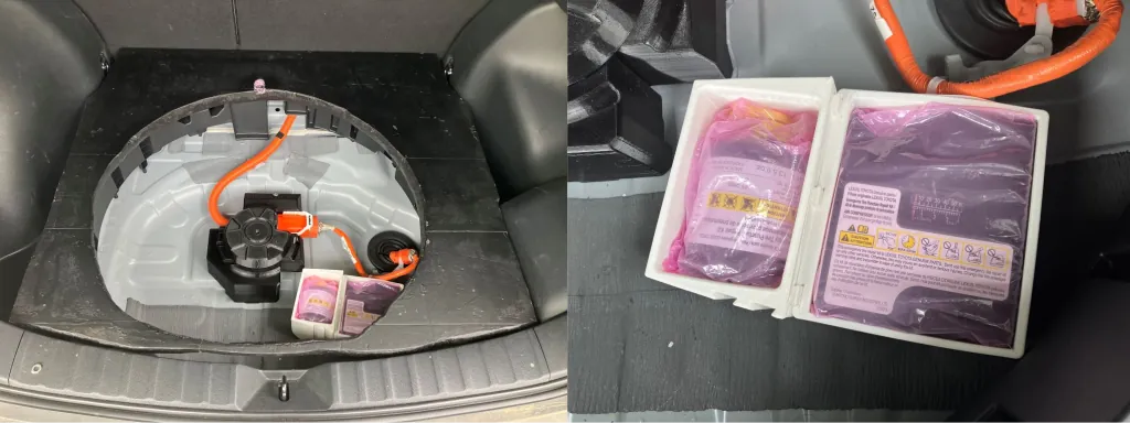
<ol>
  <li>Preheat, home, and level - <code class="language-plaintext highlighter-rouge">G280 S1</code></li>
  <li>Heat nozzles to printing temperature - <code class="language-plaintext highlighter-rouge">M109</code></li>
  <li>Prime nozzles with a line - <code class="language-plaintext highlighter-rouge">G0</code>/<code class="language-plaintext highlighter-rouge">G1</code></li>
  <li>Move to start position - <code class="language-plaintext highlighter-rouge">G0</code></li>
</ol>

<p>You must prime at least the <code class="language-plaintext highlighter-rouge">retract_length_toolchange</code> distance of filament to ensure that the <a href="https://github.com/Ultimaker/Cura/pull/18533">filament is at a known position at the beginning of the print</a>. <code class="language-plaintext highlighter-rouge">retract_length_toolchange</code> is the length of filament retraction when switching nozzles. When a new print is started, the filament position in the extruder train is unknown. It is between 0 (the nozzle tip) and <code class="language-plaintext highlighter-rouge">retract_length_toolchange</code> distance retracted into the extruder.</p>

<p>Some users may say that this can be solved by the skirt/brim/prime tower but they often do not understand the cause of this problem which is the initial unknown location of filament. If you do not ensure a known position for the filament at the beginning of the print for both nozzles, you will encounter underextrusion the first time each nozzle is used which is NOT guaranteed to be masked during the skirt/brim/prime tower. The second or third nozzle may not be used until a much higher layer in the print and the skirt and prime tower may not have enough volume to move the filament by <code class="language-plaintext highlighter-rouge">retract_length_toolchange</code> distance.</p>

<p>You can probably see how this leads to unavoidable oozing or underextrusion when the slicer assumes filament in all nozzles start at 0 distance (at the nozzle tip).</p>

<p><img src="/wp-content/uploads/2024/04/initial_nozzle_position.jpg" alt="initial nozzle position" /></p>

<p>Cura is unaware of the filament start position at the end of your start G-code and you need to retract your filament some distance to prevent oozing. I created a Cura post processing script <a href="https://github.com/Ultimaker/Cura/pull/18533">SetInitialSwitchedExtruderOffset</a> to set the correct filament distance the first time a nozzle is used.</p>

<h2 id="putting-it-all-together">Putting it all together</h2>

<p>A final working start G-code for the Ultimaker S5/S7 with Griffin header and prime lines for both nozzles:</p>

<div class="language-plaintext highlighter-rouge"><div class="highlight"><pre class="highlight"><code>; Delete the first 'generated by PrusaSlicer' line to make gcode printable on Ultimaker S-line

;START_OF_HEADER
; Printer_Settings_ID: [printer_settings_id]

;ULTIMAKER GRIFFIN HEADER
;HEADER_VERSION:0.1
;FLAVOR:Griffin
;GENERATOR.NAME:PrusaSlicer
;GENERATOR.VERSION:5.4.0
;GENERATOR.BUILD_DATE:{year}-{month}-{day}
;TARGET_MACHINE.NAME:Ultimaker S7
;EXTRUDER_TRAIN.0.INITIAL_TEMPERATURE:{first_layer_temperature[0]}
;EXTRUDER_TRAIN.0.MATERIAL.VOLUME_USED:{extruded_volume[0]}
;EXTRUDER_TRAIN.0.MATERIAL.GUID:0f12978a-8e3c-4147-b9ca-726d5ed59368
;EXTRUDER_TRAIN.0.NOZZLE.DIAMETER:{nozzle_diameter[0]}
;EXTRUDER_TRAIN.0.NOZZLE.NAME:AA {nozzle_diameter[0]}
;EXTRUDER_TRAIN.1.INITIAL_TEMPERATURE:{temperature[1] + standby_temperature_delta}
;EXTRUDER_TRAIN.1.MATERIAL.VOLUME_USED:{extruded_volume[1]}
;EXTRUDER_TRAIN.1.MATERIAL.GUID:0f12978a-8e3c-4147-b9ca-726d5ed59368
;EXTRUDER_TRAIN.1.NOZZLE.DIAMETER:{nozzle_diameter[0]}
;EXTRUDER_TRAIN.1.NOZZLE.NAME:AA {nozzle_diameter[0]}
;BUILD_PLATE.INITIAL_TEMPERATURE:[first_layer_bed_temperature]
;BUILD_VOLUME.TEMPERATURE:28
;PRINT.TIME:0
;PRINT.GROUPS:1
;PRINT.SIZE.MIN.X:{print_bed_min[0]}
;PRINT.SIZE.MIN.Y:{print_bed_min[1]}
;PRINT.SIZE.MIN.Z:0
;PRINT.SIZE.MAX.X:{print_bed_max[0]}
;PRINT.SIZE.MAX.Y:{print_bed_max[1]}
;PRINT.SIZE.MAX.Z:{max_print_height}
;SLICE_UUID:32daaf1d-f868-4a8e-ad06-8536b153e789
;END_OF_HEADER
T0
M82 ;absolute extrusion mode

G21 ; metric values
G90 ; absolute positioning
M107 ; start with the fan off

M140 S{first_layer_bed_temperature[initial_extruder]} ; start bed heating

G28 ; home if supported
G1 X1 Y6 F15000 ; move X/Y to start position
G1 Z35 F9000 ; move Z to start position

M104 S{temperature[initial_extruder] + standby_temperature_delta} ; heat nozzle

G280 S1 ; ultimaker home

;To skip adaptive bed mesh probing uncomment G0 commands before ;LAYER:1
;G0 X{print_bed_min[0]} Y{print_bed_max[1]}
;G0 X{print_bed_min[0]} Y{print_bed_min[1]}
;G0 X{print_bed_max[0]} Y{print_bed_min[1]}
;G0 X{print_bed_max[0]} Y{print_bed_max[1]}
;LAYER:1

; purge retract_length_toolchange due to unknown state
; prime extruders next to each other to verify extruder offset calibration

; prime T0
M104 S{first_layer_temperature[0]} T0 ; start heat nozzle temperature
T0
M109 S{first_layer_temperature[0]} T0 ; wait for nozzle temperature
G90
M82
G0 X5 Y100 Z0.3 F7200
G92 E0
G1 X5 Y10 E1.9 F1000
G0 X5 Y1 Z0.3 F7200
G92 E0
G1 X{print_bed_max[0]-30} Y1 E5.553 F1000
G0 X{print_bed_max[0]-30} Y1.5 F7200
G92 E0
G1 X10 Y1.5 E5.458 F1000
G0 X10 Y1.9 F7200
M104 S{temperature[initial_extruder] + standby_temperature_delta} ; cool nozzle
M104 S{first_layer_temperature[1]} T1 ; start heat next nozzle temperature
G92 E0
G1 X{print_bed_max[0]-28} Y1.9 E5.489 F1000
G92 E0
G1 E-3.5 F1200
G0 X{print_bed_max[0]-20} Y3 F18000
G0 X{print_bed_max[0]-15} Y10 Z3 F2400

G0 X30 Y10 Z0.3 F7200
G92 E0
G1 E3.5 F1200
G92 E0
G0 Y110 E1.85 F1000
G92 E0
G1 E-{retract_length_toolchange[0]} F1200
G0 Y150 F18000
G0 Y{print_bed_max[1]} Z5 F18000

; prime T1
T1
M109 S{first_layer_temperature[1]} T1 ; wait for nozzle temperature
G90
M82
G0 X5 Y100 Z0.3 F7200
G0 Y10 E1.9 F1000
G0 Y2.5 F7200
G92 E0
G1 X{print_bed_max[0]-30} Y2.5 E5.553 F1000
G0 X{print_bed_max[0]-30} Y2.9 F7200
G92 E0
G1 X10 Y2.9 E5.458 F1000
G0 X10 Y3.3 F7200
M104 S{temperature[1] + standby_temperature_delta} ; cool nozzle
M104 S{first_layer_temperature[initial_extruder]} ; start heating initial nozzle
G92 E0
G1 X{print_bed_max[0]-28} Y3.3 E5.489 F1000
G92 E0
G1 E-3.5 F1200 ;retract just a little because we don't have a way to tell the slicer T1 filament position when it starts printing from E0
G0 X{print_bed_max[0]-20} Y5 F18000
G0 X{print_bed_max[0]-15} Y15 Z3 F2400

;minus extruder1 offset X 22 which macro is not supported in start gcode
G0 X{30+nozzle_diameter[1]-22} Y15 Z0.3 F7200
G92 E0
G1 E3.5 F1200
G92 E0
G0 Y115 E1.85 F1000
G92 E0
G1 E-3.5 F1200
G0 Y150 F18000
G0 Y{print_bed_max[1]} Z5 F18000

; switch to initial nozzle
T{initial_extruder}
M109 S{first_layer_temperature[initial_extruder]} ; wait for nozzle temperature
G0 X{print_bed_max[0]-30} Y5 Z10 F7200
G0 X25 Y10 Z5
G0 X25 Y20 Z0.3
M82 ;absolute extrusion mode
G92 E0
G1 Y30 E{retract_length_toolchange[initial_extruder]} F1200 ;prime to set filament location for prusaslicer generated initial retract
G92 E0

;END of start gcode
</code></pre></div></div>

<p>This is more or less the same start G-code that I included in the PrusaSlicer profile for Ultimaker S-line.</p>

<blockquote>
  <p><strong>Note:</strong> The Ultimaker S3 has a smaller bed size than the S5/S7 so I have created a modified prime line routine for it in the released PrusaSlicer profile.</p>
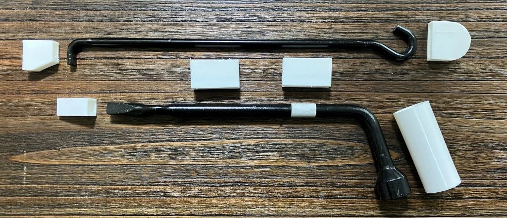
</blockquote>

<h3 id="dual-nozzle-priming">Dual Nozzle Priming</h3>

<p>After homing and leveling with <code class="language-plaintext highlighter-rouge">G280 S1</code> I added 2 sets of prime lines to prime at least \((2.85mm/2) ^ 2 * \pi * retract\_length\_toolchange[N]mm\) of material from each nozzle. <code class="language-plaintext highlighter-rouge">16mm</code> is the default retract on toolchange length for the Ultimaker. This ensures that the filament is at a known position at the end of the prime routine.</p>

<p>Both nozzles are primed next to each other so that you can visually verify that the extruder offset for the second nozzle is set correctly. <code class="language-plaintext highlighter-rouge">22mm</code> is the default second extruder X offset for the Ultimaker S-line dual nozzle printhead.</p>
<p>Ultimaker S-line firmware does not automatically apply extruder X/Y offsets to coordinates 😤 so PrusaSlicer must be set up to add/subtract extruder offsets to all coordinates when the active extruder is not the first extruder. PrusaSlicer does not allow start G-code variables to access the extruder offset so these values are currently hardcoded into the start G-code prime routine.</p>
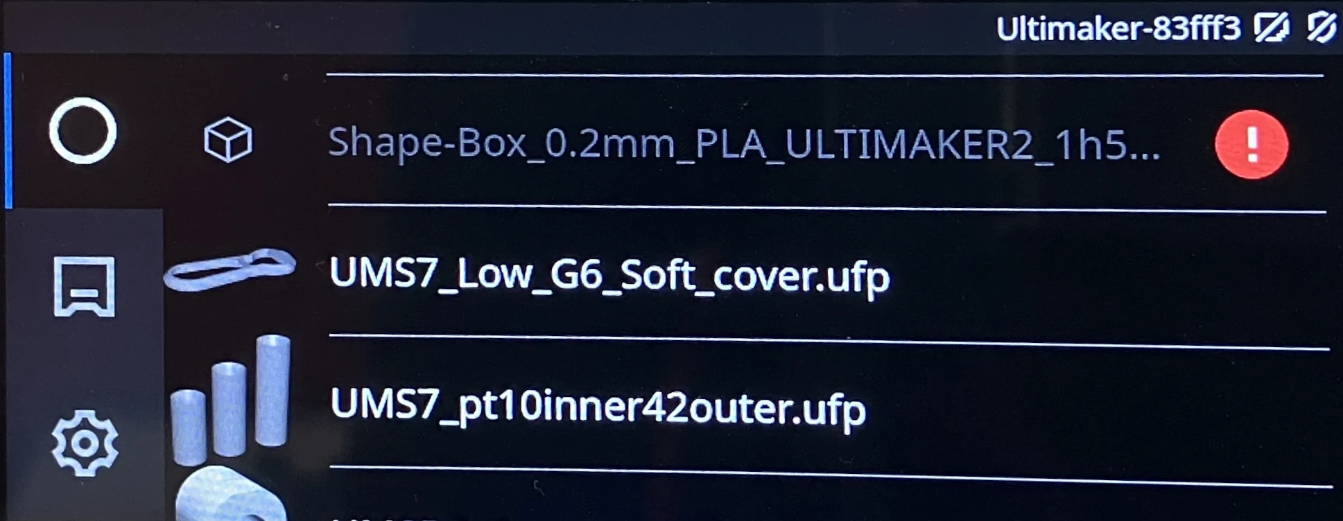

<h2 id="toolchange-g-code">Toolchange G-code</h2>

<p>Ultimaker firmware automatically adjusts the Z-offset to match the active extruder Z offset when <a href="https://marlinfw.org/docs/gcode/T.html"><code class="language-plaintext highlighter-rouge">TXX</code></a> is called with <code class="language-plaintext highlighter-rouge">XX</code> being the active extruder index.</p>

<p>I have modified the toolchange Gcode in the PrusaSlicer Ultimaker S-line printer profile to perform a Z-lift by moving the bed down for safety at the start of each toolchange to prevent nozzle collisions from new Z-offset that is instantly applied. Collisions may occur if the new active nozzle has a lower Z-offset relative to the old nozzle.</p>

<h2 id="required-post-processing---yes--you-the-user--read-this">Required Post Processing - 🫵Yes — you, the user — read this!</h2>

<p>PrusaSlicer adds the below header line to every exported G-code file:</p>

<div class="language-plaintext highlighter-rouge"><div class="highlight"><pre class="highlight"><code>;generated by PrusaSlicer
</code></pre></div></div>

<p>You must manually remove this line or any similar auto added line that comes before the actual start G-code because the Ultimaker S-line firmware will check for this line and say that G-code file cannot be printed because it contains an “error”.</p>

<h2 id="the-merging-is-complete">The Merging Is Complete</h2>

<p>This new Ultimaker printer profile keeps all the Ultimaker printers including the existing Ultimaker 2 in the old profile under a single unified profile. Some print profile settings values were updated to reflect current recommended official Ultimaker Cura values that I got good results from. I also added the <a href="https://github.com/ansonl/DXU">Ultimaker DXUv2 dual nozzle mod</a> as an available printer variant inheriting from the Ultimaker 2 settings.</p>

<p>Ultimaker S3, S5, and S7 are selectable under a single printer model of <strong>Ultimaker S-line</strong> because the mechanics and firmwares of these cartesian printers is almost identical and the same goes for the print settings. The main differences between the S-line printers are summarized below:</p>

<table>
  <thead>
    <tr>
      <th>Model</th>
      <th>Print Volume</th>
      <th>Buildplate Material</th>
    </tr>
  </thead>
  <tbody>
    <tr>
      <td>Ultimaker S3</td>
      <td>230 x 190 x 200 mm</td>
      <td>Glass</td>
    </tr>
    <tr>
      <td>Ultimaker S5</td>
      <td>330 x 240 x 300 mm</td>
      <td>Glass</td>
    </tr>
    <tr>
      <td>Ultimaker S7</td>
      <td>330 x 240 x 300 mm</td>
      <td>PEI coated spring metal</td>
    </tr>
  </tbody>
</table>

<p>I submitted my <a href="https://github.com/prusa3d/PrusaSlicer-settings/tree/master/live/Ultimaker">Ultimaker S-line (S3/S5/S7) printer profiles</a> to the <a href="https://github.com/prusa3d/PrusaSlicer-settings">Prusa/PrusaSlicer-settings</a> GitHub repo and the Prusa team reviewed and <a href="https://github.com/prusa3d/PrusaSlicer-settings/pull/245">merged</a> the update about a month later.</p>

<p>A PrusaSlicer version ≥ 2.6.0 is needed to use the Ultimaker S-line (S3/S5/S7) printer profile.</p>

<p>If you have an Ultimaker S3/S5/S7 3D printer and are feeling adventurous, take the new PrusaSlicer support for Ultimaker S-line printers out for a spin!</p>

<p>A fun visual test could be using some PrusaSlicer specific surface patterns that are not available in Cura.</p>

<h2 id="limitations">Limitations</h2>

<p>Due to slicer and printer limitations, the new Ultimaker S-line profile has some special limits to keep in mind.</p>

<ul>
  <li>The extruder offset is hardcoded into the start-Gcode.</li>
  <li>Time estimates are not available.</li>
  <li>No thumbnail support.</li>
  <li>No real GUID creation for materials. You can copy GUIDs from Cura sliced G-code if needed but the GUID does not affect the actual printing.</li>
  <li>No binary G-code support. You must save G-code as ASCII.</li>
</ul>

<h2 id="z-liftwipe-on-retract-travel">Z-lift/Wipe on Retract Travel</h2>

<p>PrusaSlicer enables Z-lift on Retract which raises the nozzle slightly after retraction and before traveling to a new location. I believe that Ultimaker has not defaulted to enabling Z-lift on Retract because the Ultimaker printer bed is only being held up on one side. This cantilevered bed design sags down on the unsupported side (the front) and is more susceptible to vibration from bed movement. In my limited testing, the PrusaSlicer style Z-lift on Retract does not decrease print quality when used on the Ultimaker S7.</p>]]></content><author><name>Anson Liu</name></author><category term="development" /><category term="3d printing" /><category term="ultimaker" /><category term="firmware" /><category term="prusaslicer" /><summary type="html"><![CDATA[![Prusaslicer to ultimaker](/wp-content/uploads/2024/04/prusaslicer-ultimaker.webp) You may need [PrusaSlicer](https://github.com/prusa3d/PrusaSlicer) to slice a model to print on your Ultimaker S3/S5/S7 3D printer for a multitude of reasons: - Slicing error - PrusaSlicer specific surface patterns - Different prime tower shapes - Experimentation The Ultimaker S-line printers usually refuse to print model G-code sliced with PrusaSlicer and non-Cura slicers by default due to a special header requirement and custom homing/leveling routine. ![Prusaslicer profile supported ultimaker printers](/wp-content/uploads/2024/04/prusaslicer-ultimaker-printers.webp) I added a [PrusaSlicer Ultimaker printer profile](https://github.com/prusa3d/PrusaSlicer-settings/tree/master/live/Ultimaker) that generates the headers and start G-code needed by the Ultimaker S-line printers so that you can easily slice and print to your Ultimaker S-line printer with PrusaSlicer.]]></summary><media:thumbnail xmlns:media="http://search.yahoo.com/mrss/" url="https://ansonliu.com/wp-content/uploads/2024/04/prusaslicer-ultimaker.webp" /><media:content medium="image" url="https://ansonliu.com/wp-content/uploads/2024/04/prusaslicer-ultimaker.webp" xmlns:media="http://search.yahoo.com/mrss/" /></entry><entry><title type="html">Ford Escape Hybrid (2005-2007, 1st generation) Plug-in Cross-Charge Jumpstart</title><link href="https://ansonliu.com/2024/03/1st-gen-ford-escape-hybrid-plug-in-manual-jumpstart/" rel="alternate" type="text/html" title="Ford Escape Hybrid (2005-2007, 1st generation) Plug-in Cross-Charge Jumpstart" /><published>2024-03-30T00:00:00+00:00</published><updated>2024-03-30T00:00:00+00:00</updated><id>https://ansonliu.com/2024/03/1st-gen-ford-escape-hybrid-plug-in-manual-jumpstart</id><content type="html" xml:base="https://ansonliu.com/2024/03/1st-gen-ford-escape-hybrid-plug-in-manual-jumpstart/"><![CDATA[<p>A 1st generation (2005-2007) <a href="https://en.wikipedia.org/wiki/Ford_Escape">Ford Escape</a> Hybrid with a “dead” 330V high voltage (HV) battery can be manually charged from wall outlet with the use of a 12V charger when the voltage has dropped extremely low.</p>

<p>Most Ford Escape Hybrids from 2005-2007 are still using the original hybrid battery packs in 2024. Very impressive performance for 18 years of discharging and charging.</p>

<p><em>Proceed at your own risk! You are recommended to go to a certified dealer to service your vehicle.</em></p>

<blockquote>
  <p>The “shore power” cross charging method described further down in this post could be used to top off the hybrid battery under normal circumstances in theory - effectively turning the 1st generation Ford Escape Hybrid into a low capacity plug-in hybrid.</p>
</blockquote>

<p>When the Ford Escape Hybrid is not driven for long periods of time, the vehicle’s 330V HV nickel metal hydride (NiMH) battery loses charge and the decrease in voltage may make the vehicle unable to fully start. Symptoms are:</p>

<ul>
  <li><em>STOP SAFELY</em> message in the dashboard display</li>
  <li>Service Soon (yellow wrench) instrument cluster light on</li>
  <li>Engine does not start when turning the ignition</li>
  <li>Repeated clicking sounds when turning the ignition</li>
  <li>Loss of engine power when driving</li>
  <li>Brake pressurization lagging sounds</li>
  <li>Engine misfiring/skipping at high (normally &gt;3000) RPMs due to lack of power boost from the battery</li>
</ul>

<p>Anyways, we know why you are reading this post. Let’s jump into it.</p>

<h2 id="quick-and-easy-solution">Quick and Easy Solution</h2>

<p>Sometimes an older 330V or 12V battery needs a few minutes and warmer temperatures to provide a higher voltage. Unfortunately the Ford Escape Hybrid does not tell you which battery has low power so you’ll need to figure out as mentioned further down.</p>

<ol>
  <li>Remove the key from the ignition.</li>
  <li>Open the driver’s door and then close it. This turns off power to 12V accessories such as the radio to prevent power draw.</li>
  <li>Wait 5-10 minutes for the batteries’ voltages to rise.</li>
  <li>Insert key into ignition.</li>
  <li>Turn key in ignition and hold for ~5 seconds.</li>
</ol>

<p>If the vehicle engine starts up, drive around with the HVAC selector set to the orange Defroster or Max A/C settings to keep the engine on and charge the batteries a bit.</p>

<p>If the vehicle engine does not start up, it is time to try to raise the HV battery voltage as described below.</p>

<h2 id="hv-battery-jump-start-button">HV Battery Jump Start Button</h2>

<p>The 1st generation Ford Escape Hybrid has an HV jump start button located inside the driver side foot well.</p>

<p>This button will connect the 12V and 330V batteries for eight minutes and allow the 12V battery to charge the 330V battery. I have never purposely tested or been able to confirm if it will allow power to flow the opposite direction for the 330V battery to charge the 12V battery.</p>

<p><img src="/wp-content/uploads/2024/03/ford-escape-hybrid-jump-start-button.jpg" alt="Ford Escape Hybrid jump start button" /></p>

<p>There are <a href="https://electricvehicleforums.com/forums/ford-escape-hybrid-26/2007-ford-escape-hybrid-won-t-start-100-whoever-gives-me-right-solution-32812/index2.html">some</a> <a href="https://electricvehicleforums.com/forums/ford-escape-hybrid-26/jump-start-ford-escape-hybrid-big-pac-2987/index2.html">threads</a> on the Ford Escape Hybrid jump start function making for additional reading for the user that could be helpful for background and alternative solutions if you can get past the drama in the first thread.</p>

<h3 id="accessing-the-jump-start-button">Accessing the Jump Start Button</h3>

<p>Open the access panel in the driver side foot well.</p>

<h2 id="cross-charging-solution">Cross Charging Solution</h2>

<p>If you recently replaced the car’s 12V battery, there is a higher chance that the 330V HV battery has low charge.</p>

<ol>
  <li>Remove the key from the ignition.</li>
  <li>Open the driver’s door and then close it.</li>
  <li>Open the access panel in the driver side foot well.</li>
  <li>Press the jump start button. The LED on the button should blink slowly.</li>
  <li>Wait 8 minutes.</li>
  <li>Insert key into ignition.</li>
  <li>Turn key in ignition and hold for ~5 seconds.</li>
</ol>

<p>If the vehicle starts, drive around a bit to charge the HV battery.</p>

<p>If the vehicle does not start, the 330V battery voltage may be so low that one eight minute charge cycle did not provide enough power for starting purposes.</p>

<p>Depending on how confident you are in the power level of the 12V battery, you can try pressing the jump start button again and repeating the steps. However at this point, you risk draining the 12V battery and ending up with two discharged batteries. It may be time to use “<a href="https://en.wikipedia.org/wiki/Shore_power">shore power</a>” to provide the power to charge the HV battery.</p>

<h2 id="shore-power-hv-battery-cross-charging-and-jump-start">Shore Power HV Battery Cross Charging and Jump Start</h2>

<p>An external 12V power source will be used to charge the 330V battery and bring it up to the needed voltage.</p>

<p>Hooking up an external 12V power source to the 12V battery will supplement the 12V battery power and provide power during the eight minute jump start button charge cycle.</p>

<p>Connect a wall powered 12V battery charger (or another running vehicle’s 12V battery) to the Ford Escape Hybrid’s 12V car battery. If possible, set the current setting on the charger to 10A or lower. A lower current setting than the typical 50A jumpstart will allow a persistent power flow to the 330V battery through the 12V battery.</p>

<p>Since most chargers and household outlets are rated at 120W or 10A of power output a higher current jumpstart mode results in the charger saving power in a capacitor to deliver 50A+ at once. You don’t want this mode, since the charger may not output consistent power.</p>

<dl>
  <dt><img src="/wp-content/uploads/2024/03/harborfreight-charger.jpg" alt="12V charger" /></dt>
  <dd><em>An example of a 12V charger that works for cross charging the batteries.</em></dd>
</dl>

<p>The shore power cross-charging setup is below:</p>

<div class="language-plaintext highlighter-rouge"><div class="highlight"><pre class="highlight"><code>12V charger -&gt; 12V car battery -&gt; jump start cross-charger -&gt; 330V hybrid battery
</code></pre></div></div>

<p>The combined steps are below:</p>

<ol>
  <li>Remove the key from the ignition.</li>
  <li>Open the driver’s door and then close it.</li>
  <li>Open the access panel in the driver side foot well.</li>
  <li>Connect a wall powered 12V battery charger to the 12V car battery.</li>
  <li>Set the battery charger to 10A mode.</li>
  <li>Verify that the voltage reading on the charger is at 12V or in the green zone. This will show the voltage of the 12V car battery which should be near full voltage.</li>
  <li>Press the jump start button. The LED on the button should blink slowly.</li>
  <li>Verify that the voltage reading on the charger is lowered due to the power flowing into the 330V battery. The voltage shown on the charger may drop down to 0 which is expected since the 330V battery is consuming all the charging power and no power is flowing backwards the positive side from the 12V car battery.</li>
  <li>Wait 10 minutes.</li>
  <li>Verify that the voltage reading on the charger is at 12V or in the green zone.</li>
  <li>If you think that the 330V battery has been charged long enough, proceed to the next step. Otherwise, go to step 6. The number of charge cycles needed depends on how many days or weeks the 330V battery has been discharging.</li>
  <li>Set the charger to 50A+ jumpstart mode if available.</li>
  <li>Insert key into ignition.</li>
  <li>Turn key in ignition and hold for ~5 seconds.</li>
</ol>

<p>If the car starts, disconnect the battery charger from Ford Escape Hybrid car battery and drive the car around to charge the batteries more.</p>

<p>If the car still fails to start, the 330V or 12V batteries may have too low of a voltage and require additional voltage boosting with an external battery charger. You can do more jump start charge cycles and/or charge slower at the lower amp setting to protect battery health over a few hours or days. You will need to remember the press the jump start button to resume charging after 10 minutes (which is after previous charge cycle completes).</p>

<h2 id="finding-other-faults">Finding Other Faults</h2>

<p>Additionally, the vehicle batteries may not be the cause of the starting issue. Reading the vehicle’s trouble codes with an OBD scanner may reveal other problem preventing the vehicle’s start. No trouble codes were returned to my Ultragauge scanner when I encountered this low voltage issue.</p>

<h2 id="how-to-prevent-low-voltages-in-the-future">How to Prevent Low Voltages in the Future</h2>

<p>Drive the Ford Escape Hybrid regularly. Regularly means using the Escape as your daily driver for long drives.</p>

<p>To be establish a safe upper bound, regularly does not mean leaving the car unused for 2 weeks. Even 1 week of battery discharge is pushing it. The longer you let the car sit between use, the longer you need to drive it or cross-charge it to keep the battery voltage up.</p>

<p>You could replace the hybrid battery pack with a refurbished battery pack but the shipping and labor cost may not be economical for a 18 year old car. After all, no car lasts forever on original parts. The 1st generation Ford Escape Hybrid has lasted much longer than many other non-hybrid vehicles on the road so replacing and recycling the hybrid battery is an expected expense similar to a transmission or engine replacement that one may encounter for a non-hybrid vehicle of similar age and usage.</p>

<p>If you’re driving a 1st gen Ford Escape Hybrid in 2024, you probably paid it off or bought it cash. With preventative maintenance such as engine, <a href="/2021/12/ford-escape-hybrid-ecvt-flush-fill/">eCVT transmission</a>, <a href="/2021/12/ford-escape-hybrid-ptu-fluid-change/">PTU</a>, and <a href="/2021/11/ford-escape-rear-differential-fluid-flush-fill/">differential</a> oil changes, a mechanically sound Ford Escape Hybrid may have a few hundred thousand more miles left in it at a rock bottom cost-of-ownership.</p>

<h2 id="ford-escape-hybrid-heaven-onto-the-3rd-owner">Ford Escape Hybrid Heaven (onto the 3rd owner)</h2>

<p>This is likely my last Ford Escape Hybrid post. I recently purchased a <a href="https://en.wikipedia.org/wiki/Toyota_Corolla_Cross">Toyota Corolla Cross Hybrid</a> S AWD due to having less time to maintain and tinker with vehicles and wanting new quality of life features of adaptive cruise control and Carplay.</p>

<p>I previously added an AUX audio input to the Ford Escape Hybrid headunit in my <a href="/2017/09/ford-acp-cd-changer-emulator-aux-audio/">Ford ACP AUX</a> <a href="https://github.com/ansonl/FordACP-AUX">project</a>. Basically my poor man’s substitute for Carplay.</p>

<p><em>Why didn’t I buy a new Ford vehicle?</em></p>

<p><a href="/2022/10/2021-ford-bronco-sport-base-vs-2007-escape-hybrid/">I’m not impressed with the Bronco Sport</a> after driving a rental on a road trip and Ford’s current hybrid/plug-in hybrid vehicles are nerfed to not include AWD or omit adaptive cruise and other safety features that should be standard in 2024. Other models I shopped for were the current hybrid Escape (ugly compared to Bronco, no plug-in AWD) and Maverick (markups or long wait, no hybrid AWD). Ford’s current 2024 models and trims are just not cost or feature competitive with other manufacturers such as Subaru, Mazda, and Toyota.</p>

<p><em>Why didn’t I buy a Subaru or Mazda?</em></p>

<p>No reliable hybrid models avaiable at the end of 2023.</p>

<p><em>Why didn’t I buy a Toyota RAV4 hybrid?</em></p>

<p>I looked for a new car similar to the 1st gen Ford Escape size and all car models have been getting the <a href="https://www.youtube.com/watch?v=jN7mSXMruEo">supersize me</a> diet since 2000. It was hard to find a RAV4 hybrid/prime with no markup. The Corolla Cross Hybrid had most of the features I wanted at a lower cost and still looks cool. The barebones S trim that I ultimately got reminds me of an older car or a work truck trim that still has analog dials and physical controls.</p>

<p>My yearly cost of ownership for the 2007 Ford Escape Hybrid 4WD over 7 years was roughly $1500-2000/yr. This number includes buying price + tax, selling price, maintenance, and upgrades. I only included cost for vehicle specific tools such as the oil filter wrench.</p>]]></content><author><name>Anson Liu</name></author><category term="Development" /><category term="jumpstart" /><category term="plug-in" /><category term="ford" /><category term="escape" /><category term="hybrid" /><summary type="html"><![CDATA[A 1st generation (2005-2007) Ford Escape Hybrid with a "dead" 330V high voltage (HV) battery can be manually charged from wall outlet with the use of a 12V charger when the voltage has dropped extremely low. When the Ford Escape Hybrid is not driven for long periods of time, the vehicle's 330V HV nickel metal hydride (NiMH) battery loses charge and the decrease in voltage may make the vehicle unable to start. ![ford escape hybrid jump start button](/wp-content/uploads/2024/03/ford-escape-hybrid-jump-start-button-zoomed.jpg) Look, we know why you're reading this. Let's get your Ford Escape Hybrid moving again!]]></summary></entry></feed>