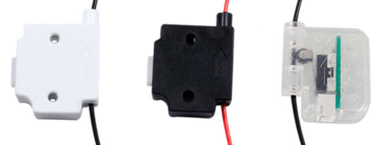
A common filament runout sensor design sold online has 3 pins but their functions are not always labeled. The sensor has a 3 pin JST-XH 2.5mm header that you would normally connect to an identical 3 pin port on your printer controller board. It’s plug and play if your controller board was designed to accomodate filament runout sensors with the same 3 pin header.
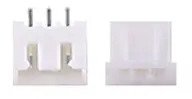
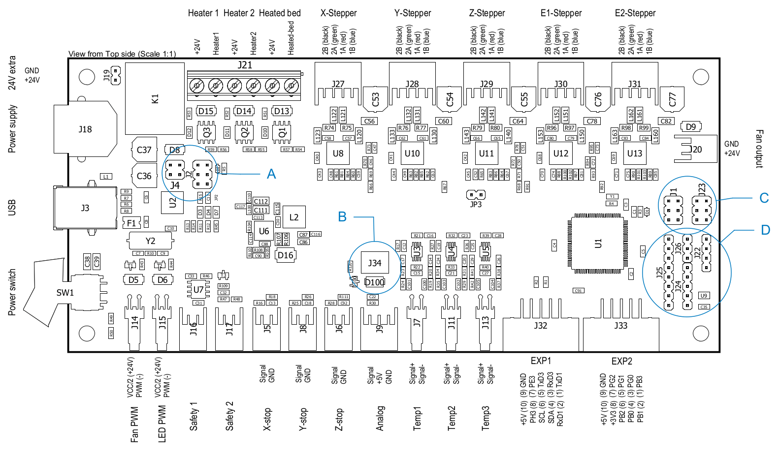
The Ultimaker Ultimainboard controller board used in the Original+ and 2/2+ does not have a labeled 3 pin JST-XH header for filament runout sensors (although it does have a 3 pin JST-XH header for an analog sensor). Instead the unused pins on the board are exposed as breakout 2.54mm headers on the right side of the board.
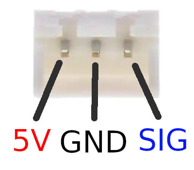
There are some conflicting resources online as to correct pin out for these generic filament runout sensors so I ended up tracing the PCB within the sensor and reverse engineered the pinout of the sensor to be +5V (VCC), GND, Signal (SIG) ordered left to right when the header is latch side up facing towards you.
The 5V pin provides a voltage to the sensor. Normally the physical switch within the sensor is disconnected and the 5V pin continually sinks to GND. Controller boards with a dedicated sensor pin will have a resistor on the 5V or GND and SIG pins to prevent over current or excessive power drain. If you use general purpose input/output pins on your board to read the filament sensor, you will need to put a resistor of high value such as 47k on the 5V line to prevent shorting the controller 5V power or sensor pin.
When a piece filament is loaded into the sensor, it runs over and presses the switch contact down. The 5V pin is connected to the SIG pin and disconnected from GND.
When filament has run out of the sensor, it no longer holds the switch contact down and the switch contact spings up, returning to its original state. The 5V pin is disconnected from SIG and current is sinked to GND again.
SIG will read LOW when filament is not present. SIG will read HIGH when filament is present.
There are some 0 Ohm resistors on the board that made reverse engineering tricky but I think the 0 Ohm components were for manufacturing uniformity and rather than obsfucation.
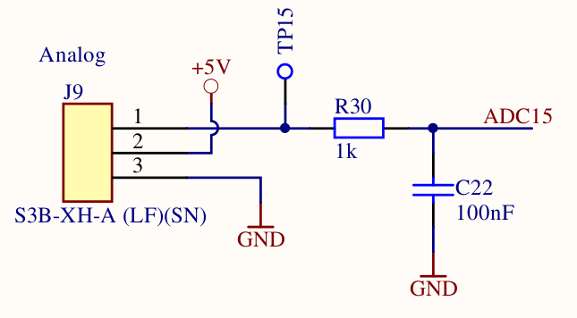
The Ultimaker Ultimainboard’s built in 3 pin analog sensor header has the pin ordering of SIG, +5V, GND. Only the SIG pin on the analog sensor header has a 1k resistor and the +5V and GND pins have no resistors to limit current. If you only need one filament sensor, you could swap the pins in the cable between the sensor and analog header to match up the +5V and SIG pins. Due to no resistor built into the board on GND, you need to either add a resistor inline to GND or +5V to prevent a short or leave GND disconnected.
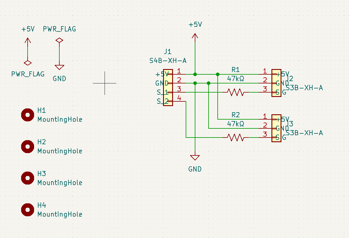
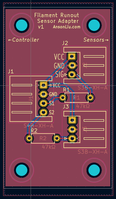
I have dual extruders on my Ultimaker and wanted to utilize the unused expansion pins on the Ultimainboard to read from 2 filament sensors. The below adapter board schematic and layout reads from 2 filament sensors using the least amount of adjacent pins on the Ultimainboard v2.
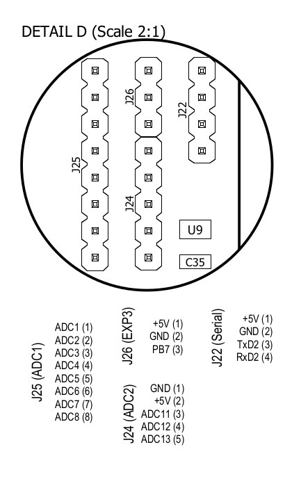
I tested this design with the below configuration using the first top 2 pins on the J25 header: ADC0 (54) and ADC1 (55). ADC0 and ADC1 are mistakenly labeled as ADC1 and ADC2 respectively in the UltiMainboard diagram above. The 5V and GND can be supplied from either J26 or J22.
For a more seamless cable setup with a single plug in point on the board, you could use 4 pins in a row on J22 to get 5V, GND, and use the TxD2 and RxD2 pins to read the sensors. You would lose the extra serial port capability.
The Marlin filament runout configuration is
#define NUM_RUNOUT_SENSORS   2
#define FIL_RUNOUT_PIN  54 // ADC0
#define FIL_RUNOUT2_PIN 55 // ADC1

#define FIL_RUNOUT_STATE     LOW
I recommend tweaking the rest of the filament configuration values to match your extruder setup and filament path lengths.
#define FILAMENT_RUNOUT_DISTANCE_MM 35

#define FILAMENT_RUNOUT_SCRIPT "M600 T%c U-20"
FILAMENT_RUNOUT_DISTANCE_MM should be large enough to allow the filament to clear the runout sensor output hole after clearing the switch contact. The switch used in the sensor only allows the filament to slide through freely from the input hole. Once the sensor switch contact springs up from no more filament passing over it, the extruder will likely destroy the switch if filament is moved backwards and get stuck underneath the switch contact’s bottom side. The runout distance should be not be too long that the filament runs past the extruder gear and looses traction.
FILAMENT_RUNOUT_SCRIPT U-XX value represents the unload length of the filament after the runout distance is exhausted. It should retract the filament back out the extruder input so you can reach it to pull it out.
