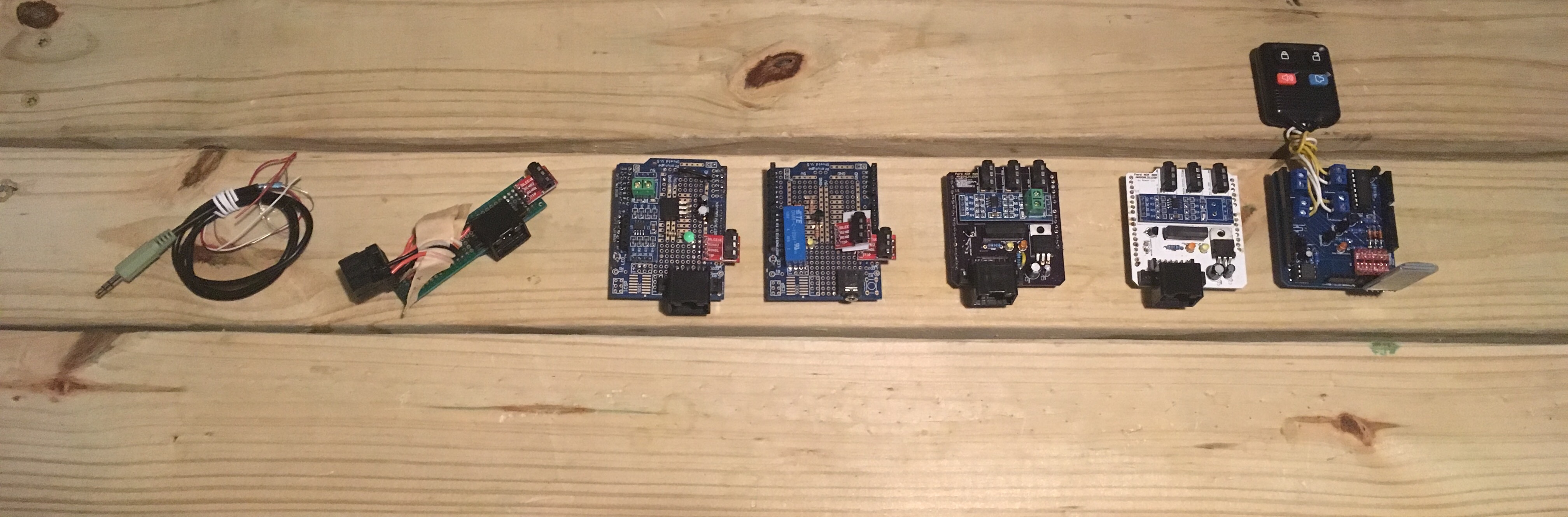
I finished an AUX audio system that plugs directly into 1996-2007 era Ford vehicle’s electrical systems and uses the original head unit controls to manage playback on iPhone. This expands upon my previous project to add an AUX audio connection to the vehicle. This open source project is available at ansonl /FordACP-AUX.
 Skip down to the demo video for the impatient.
If you are interested in interpreting Ford ACP data for energy flow/fuel efficiency info you can skip down to it here.
- Backstory
- AUX Audio version 1 - Splicing audio wires
- Ford ACP Timeline
- AUX Audio version 2 - Emulating the CD Changer with Arduino
- AUX Audio version 3 - Adding head unit playback control
- AUX Audio version 4 - Pulling It All Together
- Interpreting ACP Energy Data
- Memory Management
- Finishing Up + Demo
Backstory
Last July I added an AUX audio input to a recently acquired 2007 Ford Escape Hybrid. The reasons for adding an AUX audio input were:
- No built in AUX audio input.
- Expensive (>$50) existing third party accessories that emulated the CD changer to add AUX audio capability.
AUX Audio version 1 - Splicing audio wires
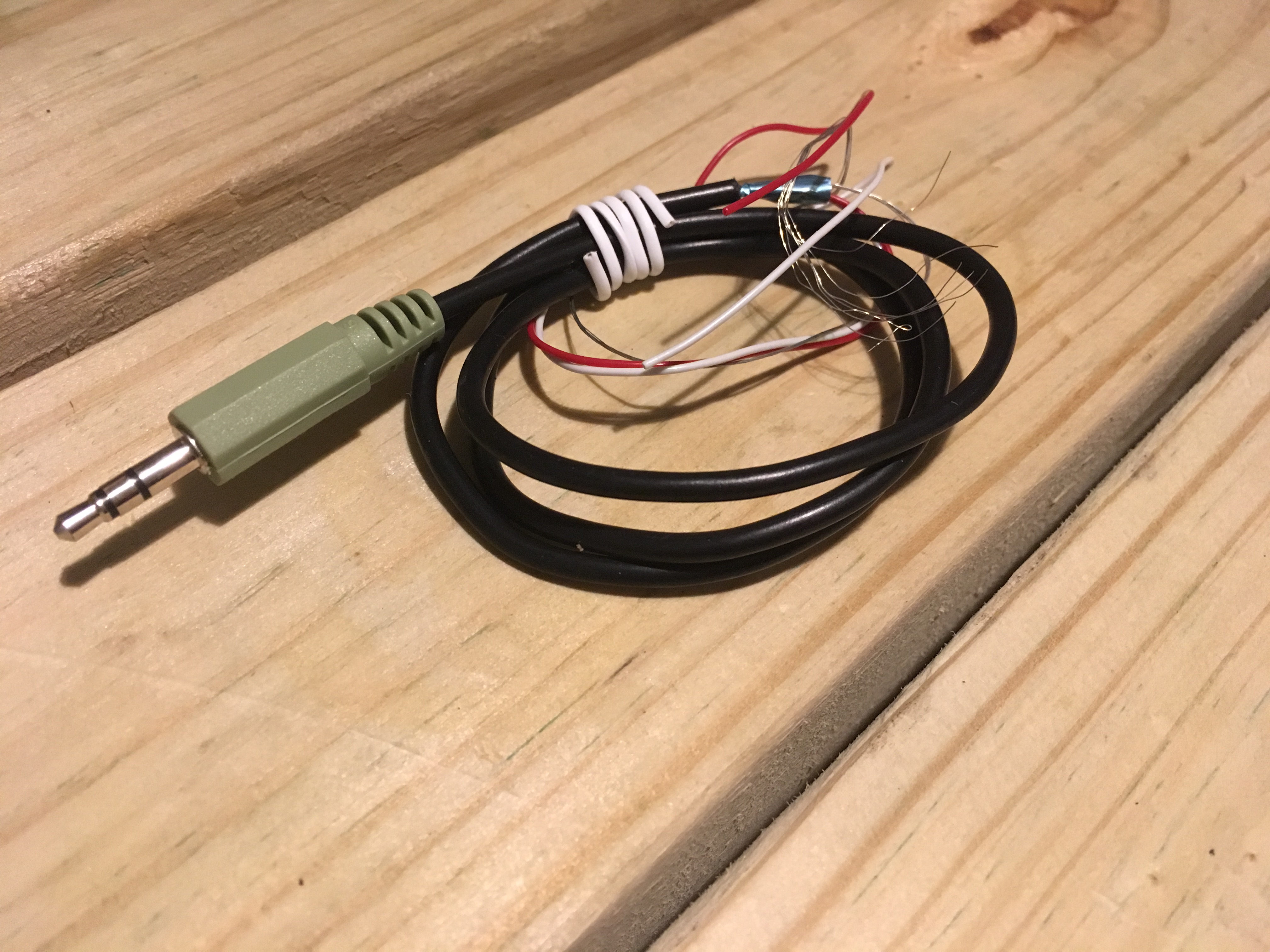
At the time, I found the correct CD changer connector pin out from a Taurus Car Club Forum post. I stripped a normal Tip Ring Sleeve (TRS) audio jack cable to expose the three wires within: Left, Right, Ground. These wires were then connected to their respective pins in the CD changer connector.
The result was an operational CD changer and a spliced in AUX audio jack for a phone.
There were a few drawbacks to the spliced in AUX audio:
- Not standalone. Reliant on original CD changer to send the “disc loaded” signal to the Ford Navigation CD Player head unit.
- Sometimes unreliable connection due to aging brittle connection wires to the head unit.
- No original Next/Previous and Fast Forward/Rewind functionality for attached audio source.
- Spliced AUX wire aesthetics.
| Current Progress | Goals |
|---|---|
| ✔ | AUX audio in |
| 🗴 | Standalone from CD changer |
| 🗴 | Reliable connection |
| 🗴 | Next/Previous and Fast Forward/Rewind functionality |
| 🗴 | Aesthetics |
Unsatisfied, I looked to create a more integrated solution for AUX audio and forgot about this for a few months after not finding more resources online.
In November 2016 I came across Krysztof Pintscher and Dale Thomas’ projects by chance ⚄.
Ford ACP Timeline
Ford Motor Corporation presents Ford Audio Communication Protocol (ACP) at SAE International Conference and Exposition.
Paper available here.
Simon J. Fisher creates acpmon.
acpmon is an ACP monitor and decoder.
Andrew Hammond creates modified yampp-3/usb firmware meant for Ford 4/5/6000 series CD Changer head unit.
The firmware allows the head unit and steering column controls to be used to control Yampp and Yampp audio to be played through the head unit.
sorban creates iPod remote control
Krysztof Pintscher ports Andrew Hammond's Yampp code to run on Arduino Mega 2560.
Dale Thomas adds AT Command integration for Bluetooth Audio support using AT Command integration with OVC3868.
Anson Liu finally does something???
AUX Audio version 2 - Emulating the CD Changer with Arduino
Krysztof and Dales’ code was made for the Arduino Mega 2560. The code would need to be modified to compile on an Arduino UNO I had. Refactoring Krysztof and Dales’ code required replacing the constants in ACP.ino to be the correct pins on the Arduino UNO.
By May 2017, I had gathered up the needed parts and modified Dale Thomas’s code to compile on Arduino UNO. The most significant steps were
Setting Up Serial
Arduino Mega 2560 serial ports
SerialSerial1Serial2Serial3
Arduino UNO serial ports
Serial
The ACP code for Arduino Mega 2560 uses the port Serial1 to communicate over RS485 for the Ford ACP protocol.
As seen, Serial must be used on the Arduino UNO. Constants for Serial1 – the “1st” Serial – must be replaced with Serial – the “0th” Serial. For example: RXEN1 → RXEN0.
Serial port is also used by Arduino for communicating with the computer via USB.
- 0 (RX) and 1 (TX) pins are connected to the microcontroller through a pair of 1K Ω resistors.
- USB logic (D+/D-) pins are connected to the microcontroller through a pair of 22 Ω resistors.
As a result, when the both USB logic and RX/TX pins are connected, the USB serial connection takes precedence.
Setting Up TX_ENABLE Pin
The ACP code for Arduino Mega 2560 uses a digital pin to control TX_ENABLE on the TTL to RS485 module.
PORTA |= (1<<PA6); //set high state on digital pin 28
PORTA &= ~(1<<PA6); //set low state on digital pin 28
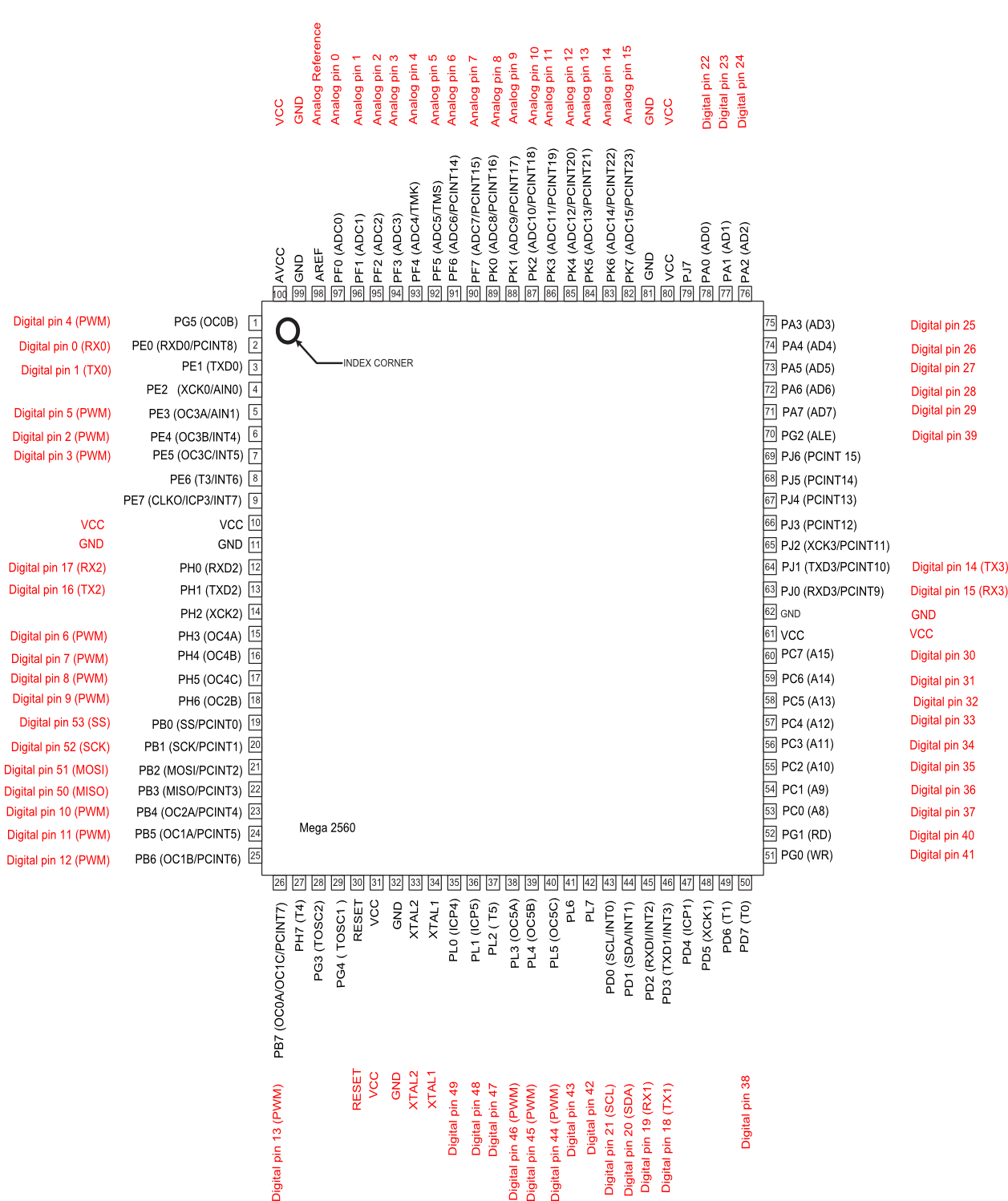
The pin is addressed by constants that rely on the Arduino Mega’s ATmega2560 pin mapping.
The first line sets pin 28 on the ATmega2560 to a high state.
(1<<PA6)returns the result of the value binary00000000with1bit shifted to the leftPA6times. ConstantPA6equals6. Returned value binary is01000000(value decimal64).PORTA |=sets thePORTAvariable to the result of a bitwise OR operation betweenPORTAand(1<<PA6). We know(1<<PA6)is01000000in binary. The result is PORTA with the bits in01000000set to1set to1.
Chart for PORTA |= (1<<PA6)
| Variable | Binary value |
|---|---|
| PORTA | 00000000 |
| & | |
| (1«PA6) | 01000000 |
| Result (PORTA) | 01000000 |
The second line sets a low state by performing bitwise AND operation on PORTA with an “opposite” NOT value of (1<<PA6).
PORTA and PA6 constants must be updated to reference a valid pin on the Arduino UNO.
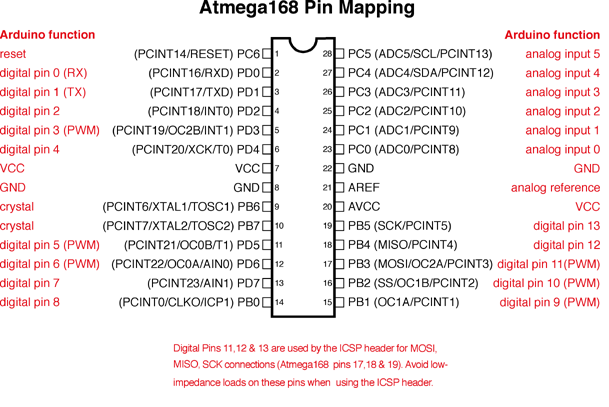
I choose to use digital pin 7 on the UNO to control TX_ENABLE. Locating digital pin 7 on the UNO ATmega328 pin mapping shows it as chip pin PD7. The D in PD7 indicates PORTD of the ATmega328 chip.
| Original | New |
|---|---|
| PORTA | PORTD |
| PA6 | PD7 |
Replace the constants.
Breadboard the Project
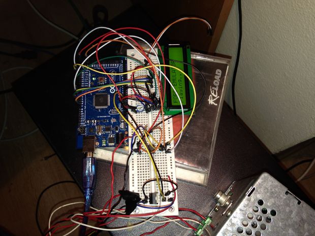
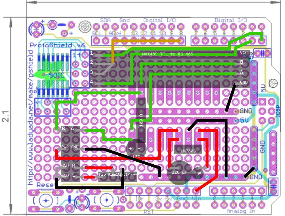
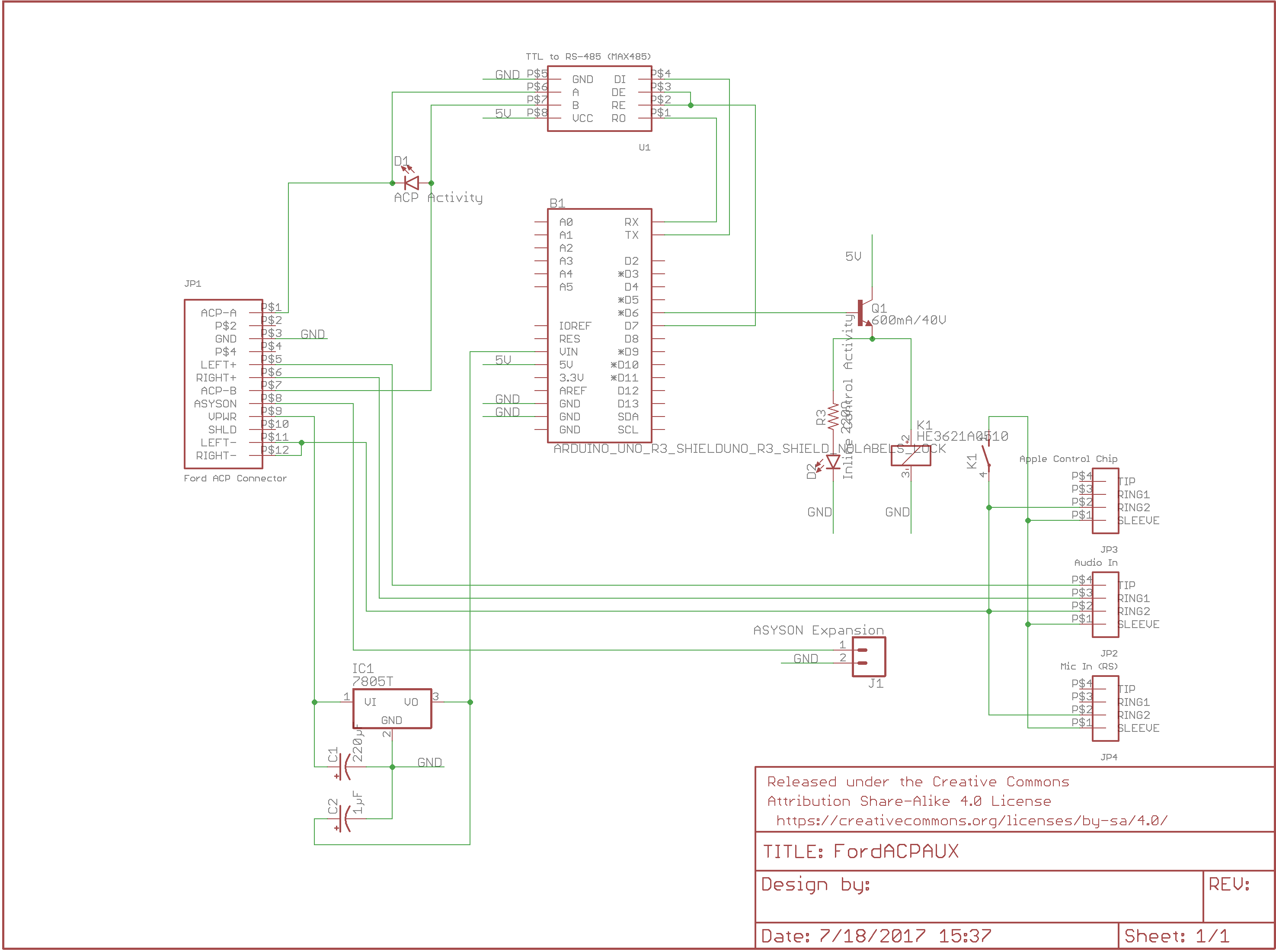
I breadboarded the circuit according to Dale Thomas’s schematic. I ignored the LCD and Bluetooth module at this step. You may need two breadboards to accomodate the rectangular TTL to RS485 module.
*IMPORTANT: Of note is that the capacitor polarity directions for the LM7805 voltage regulator shown on the schematic are incorrect and the negative end of the capacitors should be connected to ground.
| Progress | Goals |
|---|---|
| ✔ | AUX audio in |
| ✔ | Standalone from CD changer |
| 🗴 | Reliable connection |
| 🗴 | Head unit controlled Next/Previous and Fast Forward/Rewind functionality |
| 🗴 | Aesthetics |
Protoboard the Project
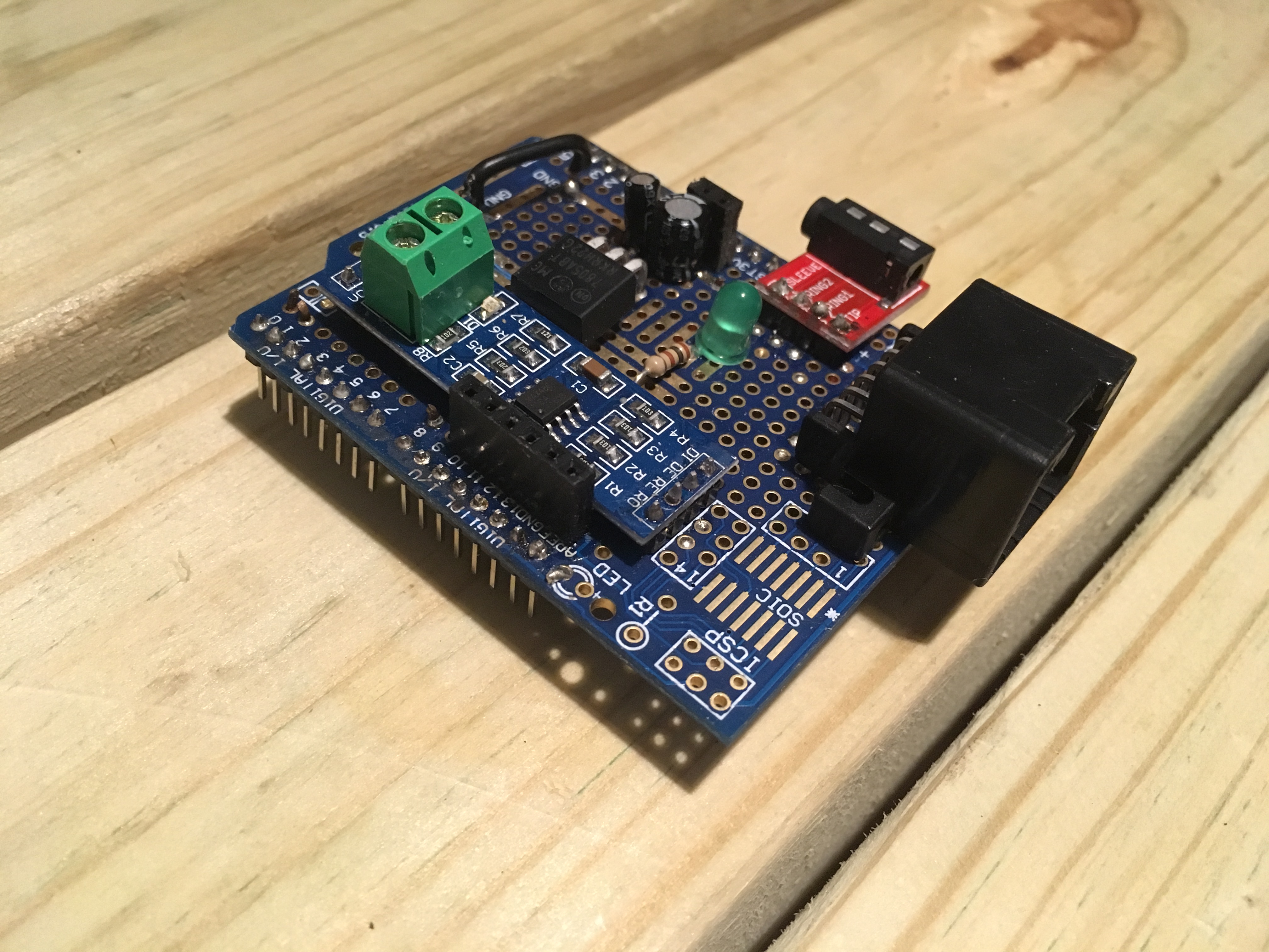
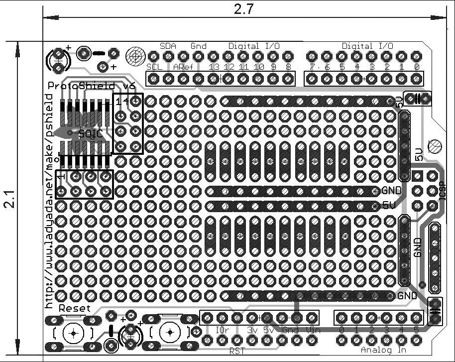
I prototyped the board on a clone protoshield based off the Adafruit Proto Shield v.5.
I used an shield fabrication print for planning wiring. To prepare the file for acceptable printing, I reversed the colors and increased the contrast. This results in a white background and darker colored circuit board pads – good for drawing on a piece of paper.
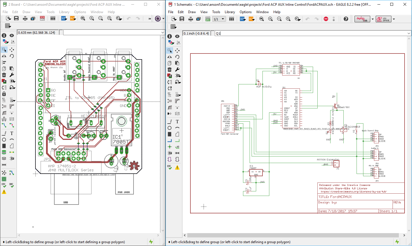
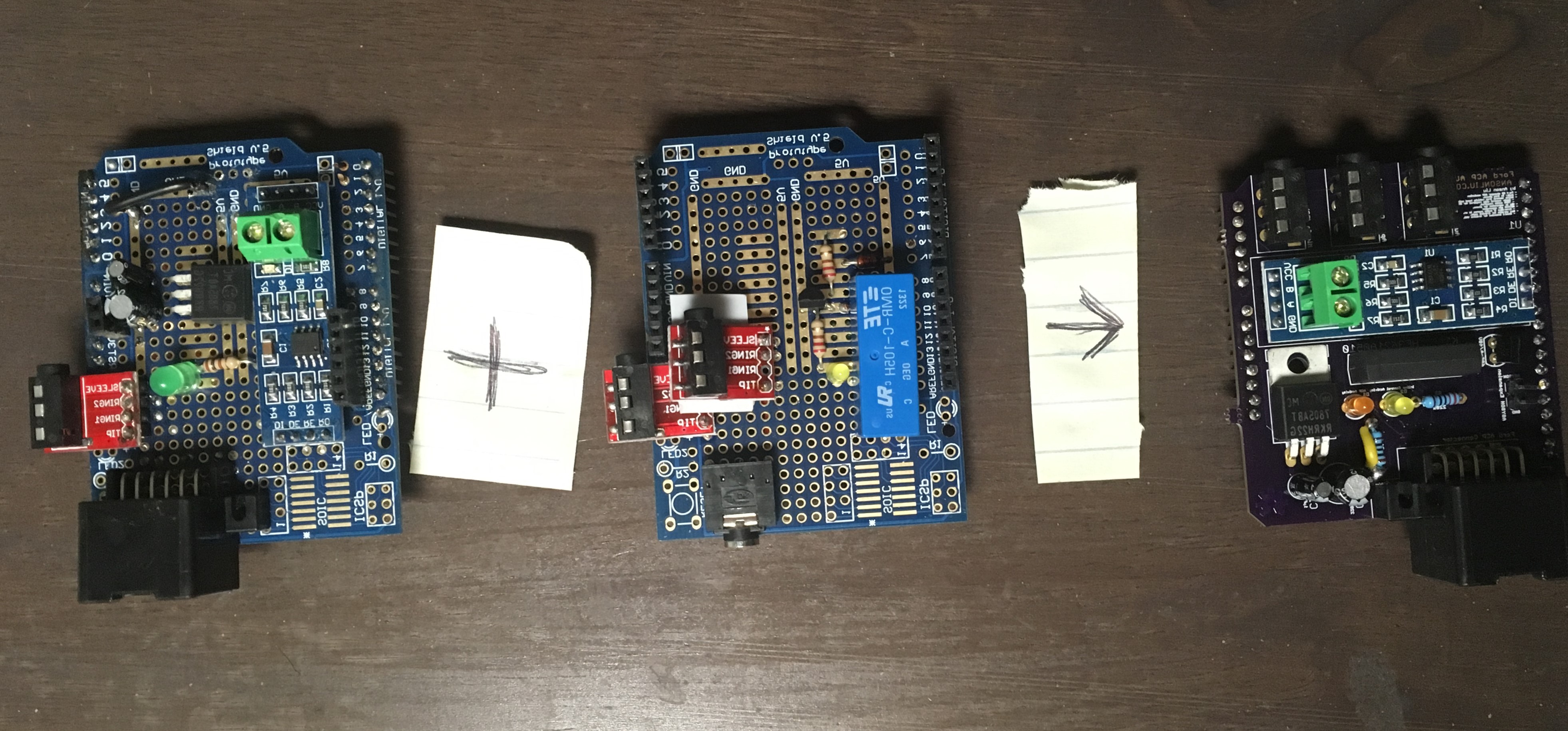
Inverted protoshield schematic for printing
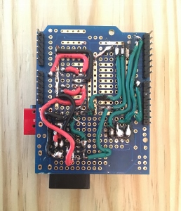
My protoshield wiring
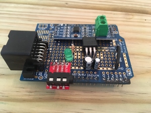
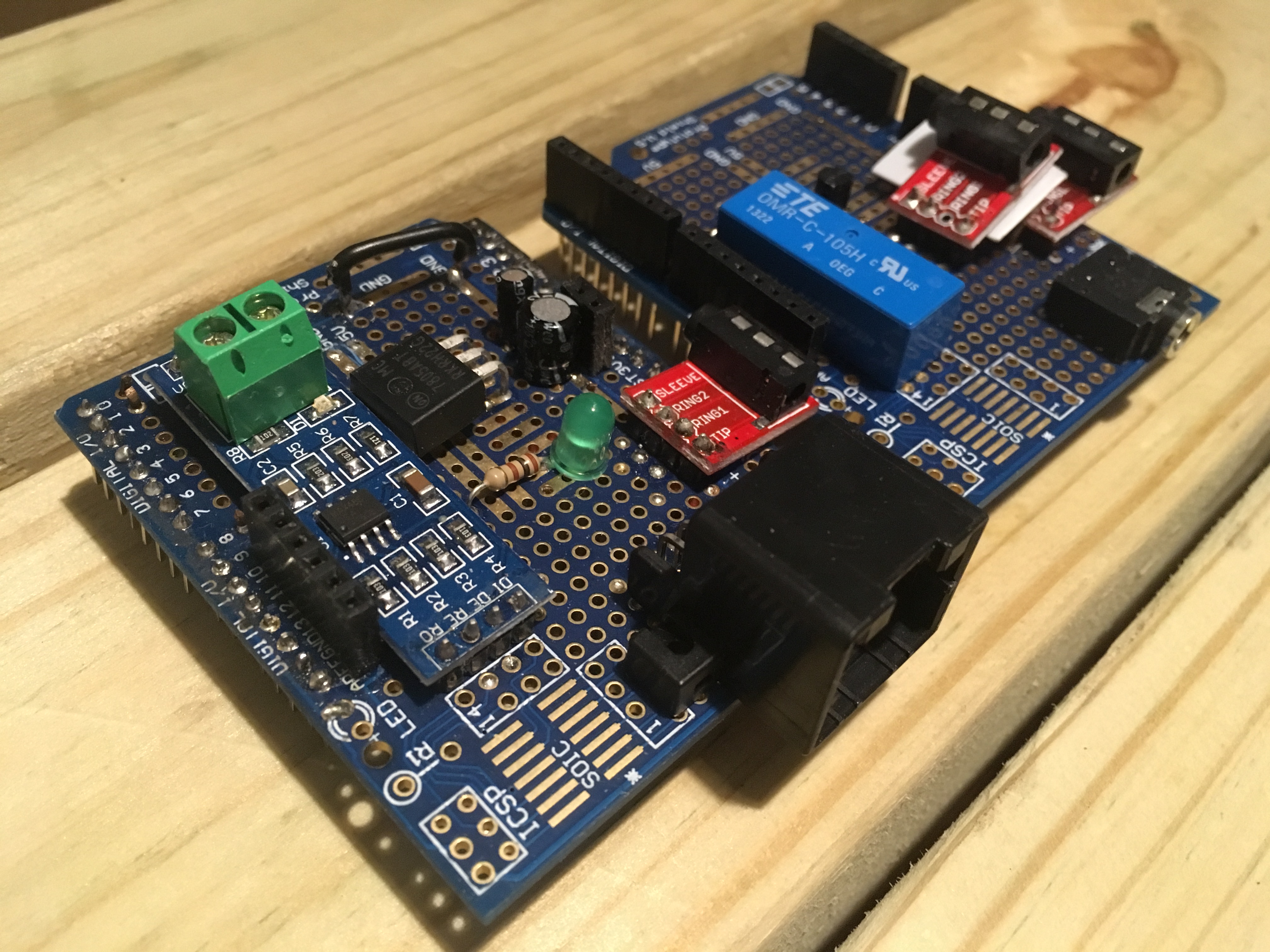
The finished protoshield
| Progress | Goals |
|---|---|
| ✔ | AUX audio in |
| ✔ | Standalone from CD changer |
| ✔ | Aesthetics |
So this looked like the end. I had completed the goal of adding a standalone AUX audio in capability that did not require the original CD changer to operate.
The setup plugged into the CD changer connector under the front passenger seat. It was out mostly out of sight but still reachable by a backseat passenger. The 12 strand twisted wire under the seat was also brittle from age and sometimes lost connectivity resulting in CDDJ Timeout error displayed on the head unit.
AUX Audio version 3 - Adding head unit playback control
All the other ACP projects implemented some sort of “control” functionality and my project hadn’t added much value. Everything I had done was remove capabilities from the other projects and fit a smaller form factor (Mega → UNO). Functionally, I hadn’t achieved more than the wire splicing of AUX Audio version 1.
Additionally, I wanted to add playback control without needing Bluetooth.
Inline Playback Control
Many Apple and third party headphones have an inline remote control containing three buttons with intended functionalities:
- Play/Pause & Next/Previous & Fast Forward/Rewind
- Volume Up
- Volume Down
In a standard stereo headphone with three connectors of Tip Ring Sleeve (TRS), 2 channels of sound are transmitted.
| Pins | Function |
|---|---|
| Tip | Left audio |
| Ring | Right audio |
| Sleeve | Ground |

Vendors’ solution to transmitting a third channel of data (ex: microphone/playback control) was to add a second ring to the connector, forming the Tip Ring Ring Sleeve (TRRS) connector.
The inline remote control headphones mentioned earlier connect to the audio source via a TRRS connector. iOS and recent (2012 and later) Android devices utilize the CTIA pinout for TRRS.
| Pins | Function |
|---|---|
| Tip | Left audio |
| Ring1 | Right audio |
| Ring2 | Ground |
| Sleeve | Microphone |
The Ring2 is simply cut out from the previous TRS Sleeve length so compatibility is preserved between TRS and TRRS.
There is also the alternative OMTP TRRS pinout that swaps the Ring2 and Sleeve functionality so that Sleeve is Ground. The OMTP pinout was initially used by Nokia and early Android devices.
Cable Chick’s Understanding TRRS and Audio Jacks is a good explanation of TRRS audio jacks with pictures.
How can we duplicate these inline control capabilities for programmatically triggered remote control?
Android Inline Control
The Android convention for playback control is pretty simple. Pressing the playback control buttons connects the Ring2 and Sleeve lines with varying resistances.
| Playback Control | Resistance (Ring2-Sleeve) |
|---|---|
| Play/Pause | 0 Ω |
| Next Track | ~ 600 Ω |
| Previous Track | ~ 220 Ω |
As you can see, Android playback control would be easy to implement if you do use an Android regularly. For reference, Rich Kappemeier created a custom remote control in 2010 for his Android. I choose not to implement controls for Android because I do not own a newer Android device.
Apple Inline Control
The Apple convention for track control is also simple on paper. Pressing the center headset button shorts the Ring2 and Sleeve lines. Shorting at specific intervals represents different commands. In David Carne’s Reverse Engineering the iPod Shuffle 3G headphone remote protocol, David lists the Volume Up/Down control buttons as inducing voltage drop between Ring2 and Sleeve.
| Playback Control | Resistance (Ring2-Sleeve) | Number of Presses |
|---|---|---|
| Play/Pause/Answer Call/Hang Up Call/Switch to New Call | 0 Ω | 1 |
| Next Track | 0 Ω | 2 |
| Previous Track | 0 Ω | 3 |
| Fast Forward | 0 Ω | 2 (Long last press for duration of fast foward.) |
| Rewind | 0 Ω | 3 (Long last press for duration of rewind.) |
| Send to Voicemail/Hang Up 2nd Call/Siri | 0 Ω | 1 (Long press) |
| Volume Up | ~ 4.7k Ω | 1 |
| Volume Down | ~ 10k Ω | 1 |
Mystery Control Chip
Merely creating a circuit to short the Ring2 and Sleeve lines fails to control a connected Apple device. If only things were that simple; there is an additional component to Apple’s headsets available as part of the Apple MFi program.
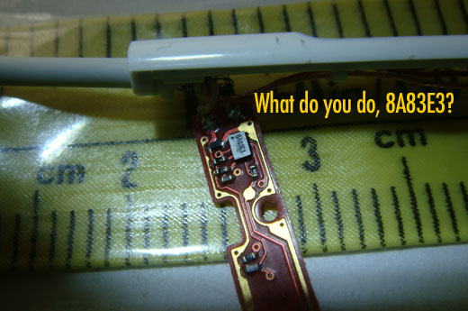
David Carne analyzed the initial connection “chirp” that the Apple headset control chip produces in his post. This “chirp” is required for the iOS device to begin accepting inline remote commands. The chirp took David a microcontroller and a small circuit to reproduce.
I did not want to spend to much time on getting the “chirp” to work at this stage and was more interested in getting the entire inline control project working. Apparently all the no-name manufacturers have created a working clone control chip to emulate the genuine Apple control chip but I wasn’t able to find any information on obtaining just the control chip. I ended up cheating by adding an additional audio port for a headset with the chip. I was able to order some headsets with inline control chip for under $2 on Ebay/dollar store.

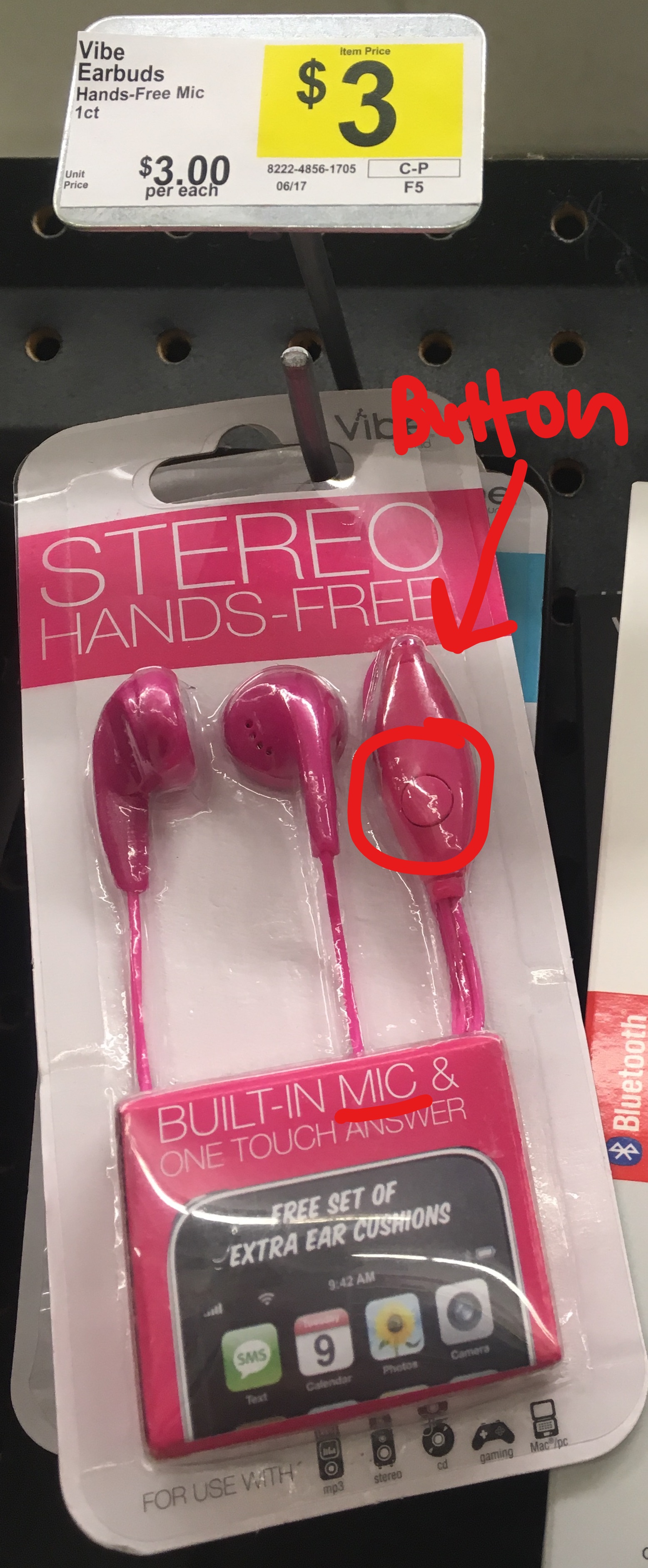
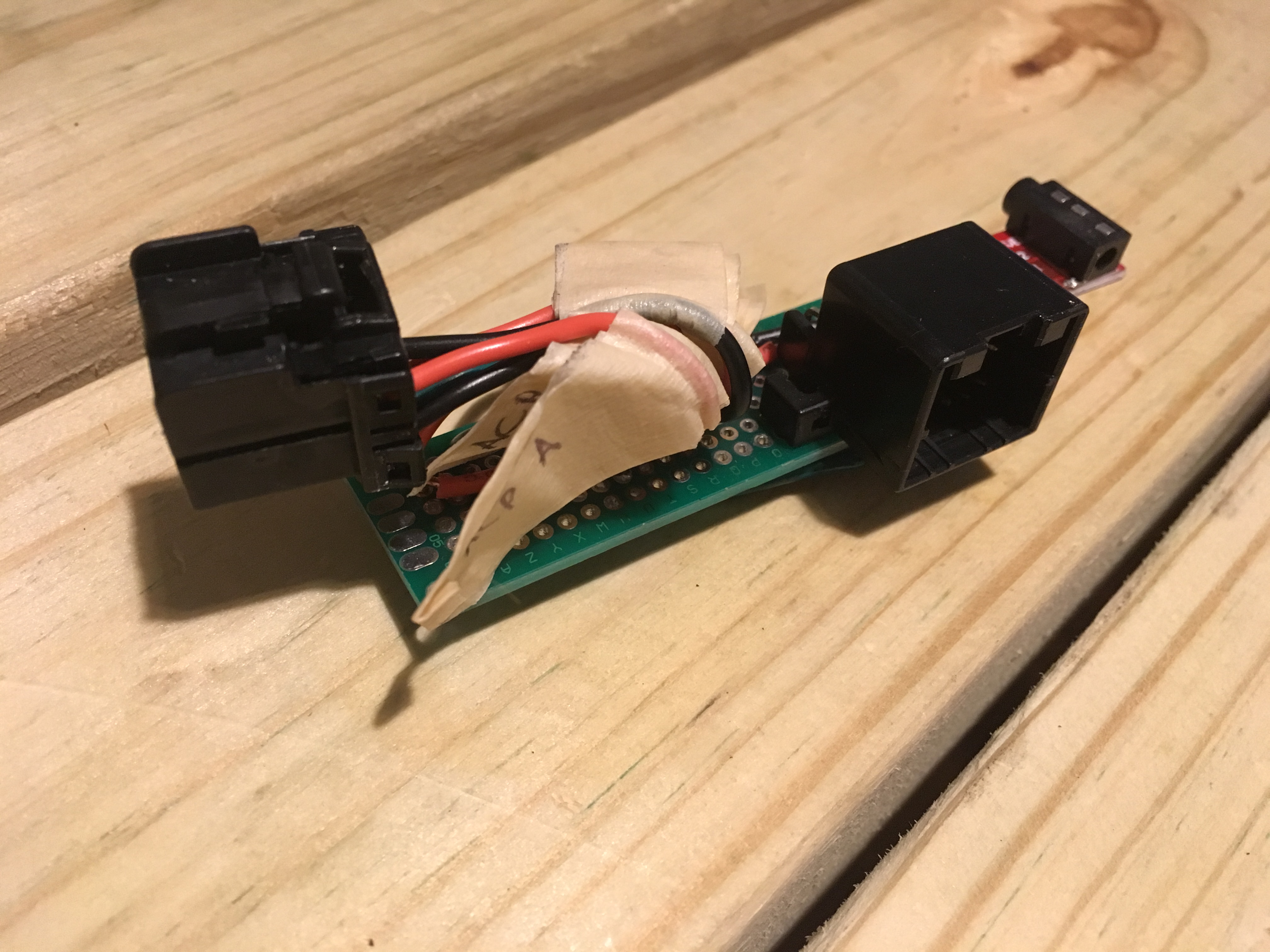
As the control chip “chirp” only occurs when the audio jack is first plugged into the iOS device, I modified my setup to have a separate TRRS audio jack just for the dongle with the control chip. This jack was connected by only Ring2 and Sleeve to another jack containing the actual TRRS cable to the iOS device.
To simulate a button press, I initially tried using a 2N2222 transistor to short Ring2 and Sleeve. For some reason the transistor did not short the two lines. Perhaps not enough current produced by the iPhone audio jack? After some more testing I was able to achieve a button press by using a reed relay. I only choose a reed relay at the time because I had on hand from a Radioshack closing sale — the reed relay was a good choice as will be explained later.
I did not emulate the volume up and down buttons as there was no need for those controls in this use case. The ACP protocol is not known to transmit volume control signals.
Because I did not design my first CD changer emulating protoboard with this in mind, I added yet another TRRS audio jack to this second protoboard to pipe the audio from the iOS device to the first shield. If you plan on hand wiring a protoboard, this can be easily avoied by having upward facing female pin headers on the bottom shield connect with bottom facing male pin headers on the top shield!
Inline Control Timing
After setting up my protoboard, I modified my previous Arduino program to execute the appropriate button press sequence upon receiving playback commands from the audio navigation system head unit.
Some testing revealed that iPhone SE is able to interpret a button press interval a small as 60 ms and that the interval must be under 200 ms to qualify for adjacent button presses to be considered part of the same sequence. I choose to use a round value of 100 ms in the program.
Back to why a reed relay was a good choice. If I had used a larger electromagnetic relay – one with a spring and arm, depending on which relay I choose, the relay might not have had a fast enough switching speed to switch every 1/10 s.
| Progress | Goals |
|---|---|
| ✔ | Head unit controlled Next/Previous and Fast Forward/Rewind functionality |
I got playback control functionality at the cost of aesthetics due to inefficient wiring — in retrospect. But hey, everything was put together and working! I had an external audio AUX input for my vehicle and could control my iPhone from the head unit.
The iPod Shuffle, iPod Classic, and laptops also support headset controls and could be used in theory.
AUX Audio version 4 - Pulling It All Together [on PCB]
What improvements could be made? I could rearrange my hand wired layout, but was getting tired of hand wiring protoboards. There were also some physical limitations to how intricately I could hand route wires.
Learning EAGLE
I learned how to use Autodesk EAGLE for printed circuit board (PCB) design using the following resources in order. Going through all three should take about 2 hours.
- KTOWN’s Ultimate Creating Parts in Eagle Tutorial
- SparkFun - Using EAGLE: Schematic
- SparkFun - Using EAGLE: Board Layout
PCB Fabrication
I used OSHPark for my first two prototype PCB orders. I ordered the minimum 3 PCBs — good for when mistakes are made.
Make sure to verify that your board pads’ drill sizes are large enough! EAGLE’s default pad drill size was too narrow.
Vehicle Wiring
In the meantime, I experimented with hiding my existing protoboard inside the body of the car by removing the head unit and plugging my protoboard directly into the head unit.
Audio works. But nothing happens when I press the fuel economy and energy flow buttons on the head unit!
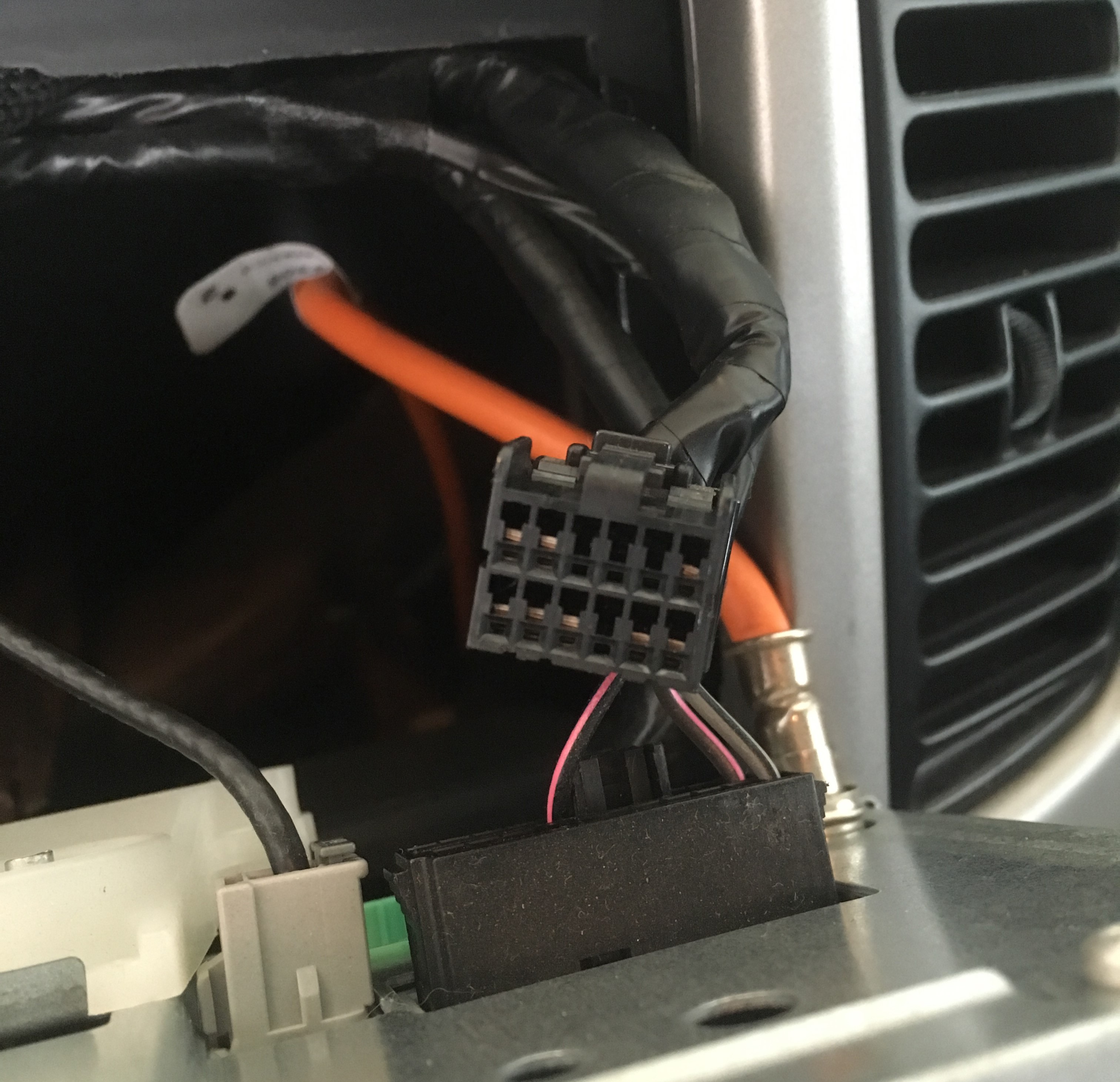
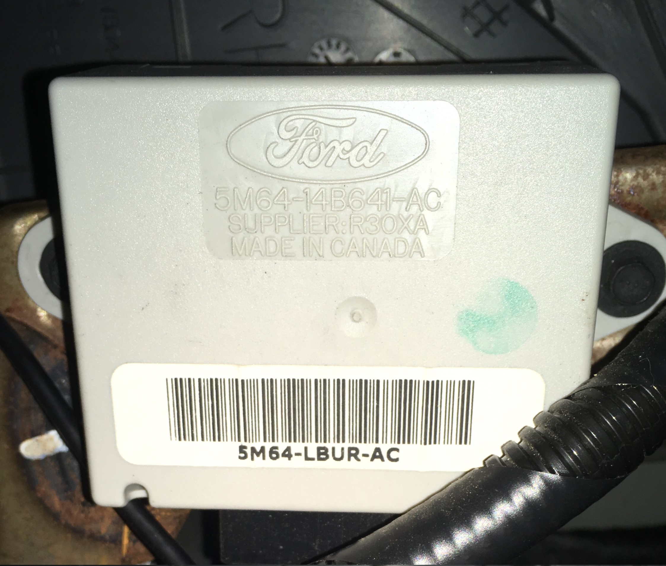
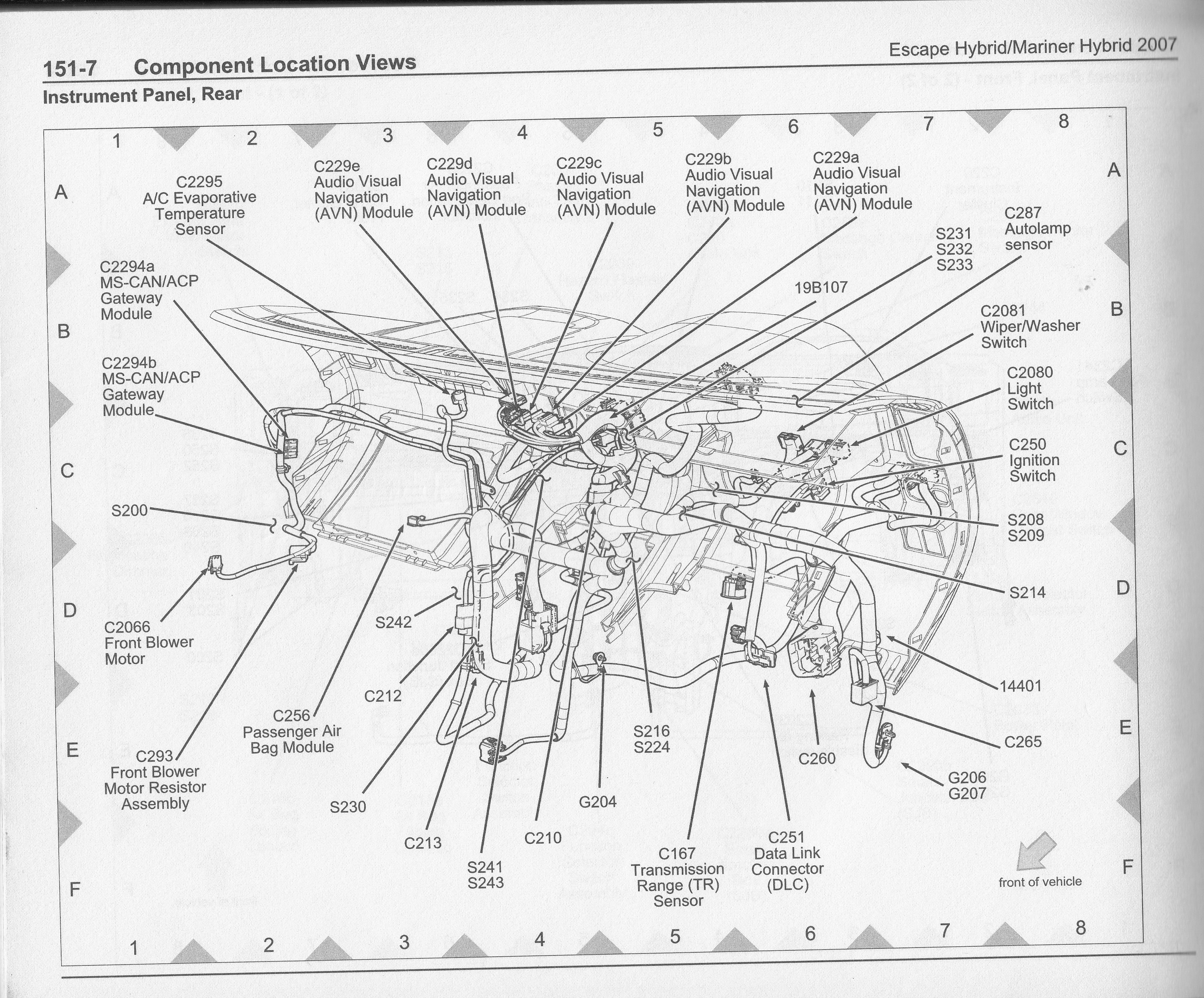
As it turns out, the hybrid vehicle contains a CAN-ACP convertor module located on the right side of the body compartment behind the glovebox. This module sends energy flow information (engine, battery charge, etc) to the nav unit to be displayed to the user.
I experimented with various ways to find correlation between the ACP data and driving events such as acceleration and braking. My results are covered below.
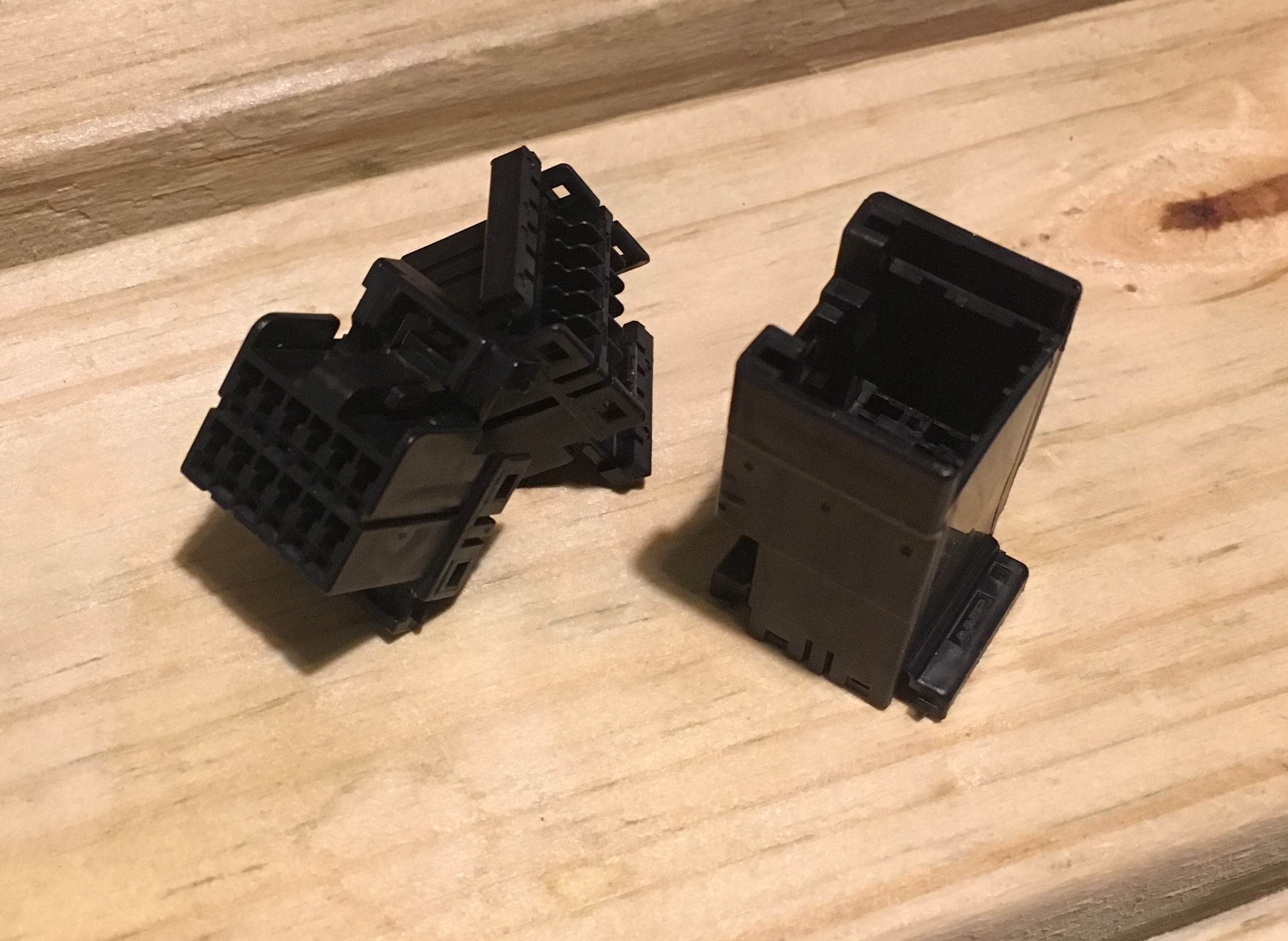
In order to place the protoboard behind the head unit, I needed to create a three 040 Multilock Connector headed cable that connected the head unit, CAN-ACP convertor, and CD changer (or CD changer emulator). The cable would consist of:
| Quantity | Type | Manufacturer Number |
|---|---|---|
| 2 | Male Connector | TE 174045-2 |
| 1 | Female Connector | TE 174058-2 |
| 24 | Receptacle Contact | TE 175180-1 |
| 12 | Tab Contact | TE 173682-1 |
The female connector listed above is a Wire-to-Wire connector. The tab contacts are crimped and slid into the connector. We used a Wire-to-Board female 040 Multilock Connector (TE 174051-2) for the protoboard. The Wire-to-Board has pins that fit into the circuit board. This connection is less bendable when squeezed behind the head unit and was difficult to solder and make solder bridges. The Wire-to-Wire connector is better suited to creating our three headed extension.
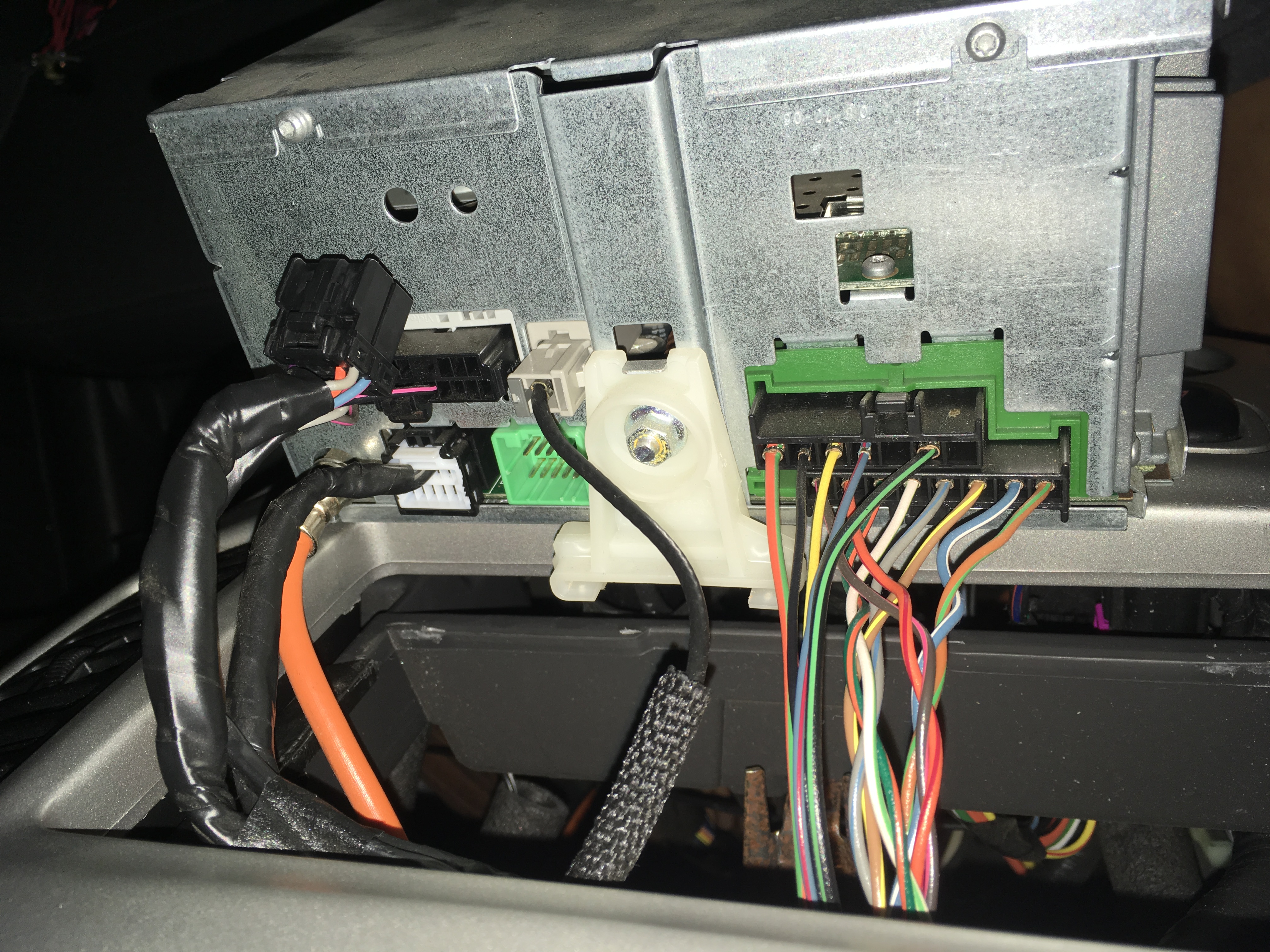
To the access the back of the Ford Escape head unit:
- Pop out the silver bezel. You can use a flathead screwdriver to do so.
- Use double DIN removal tools or wire to pull out the head unit.
- If the tools do not work for you, the plastic side wall holding the head unit can be conveniently drilled through to provide access to the clips holding the head unit.
- Any drilled holes will be covered up by replacing the silver bezel.
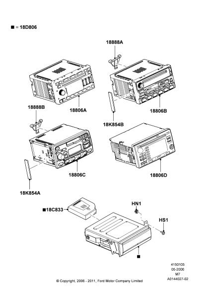
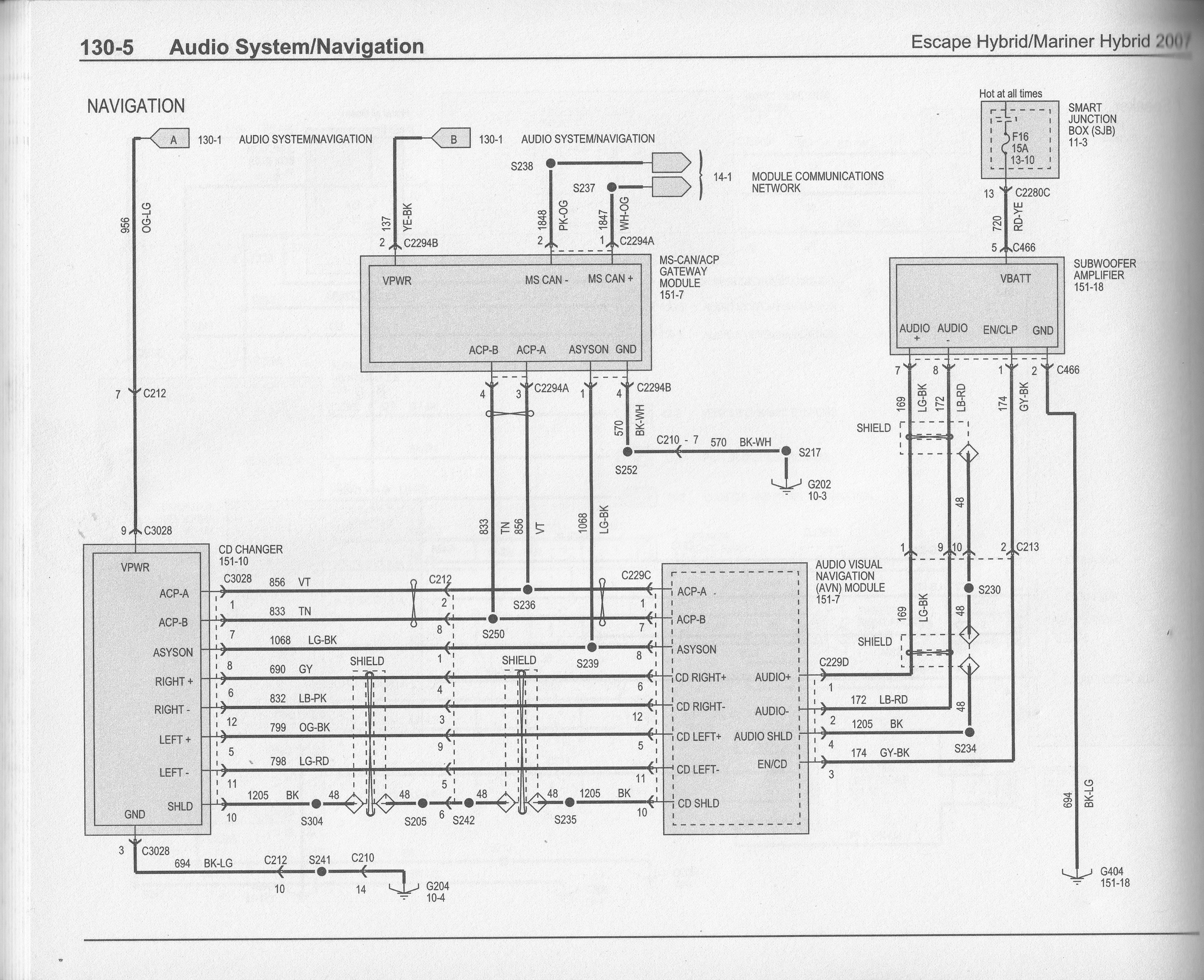
2007 Ford Escape Hybrid wiring diagram and component locations
| Progress | Goals |
|---|---|
| ✔ | Reliable connection |
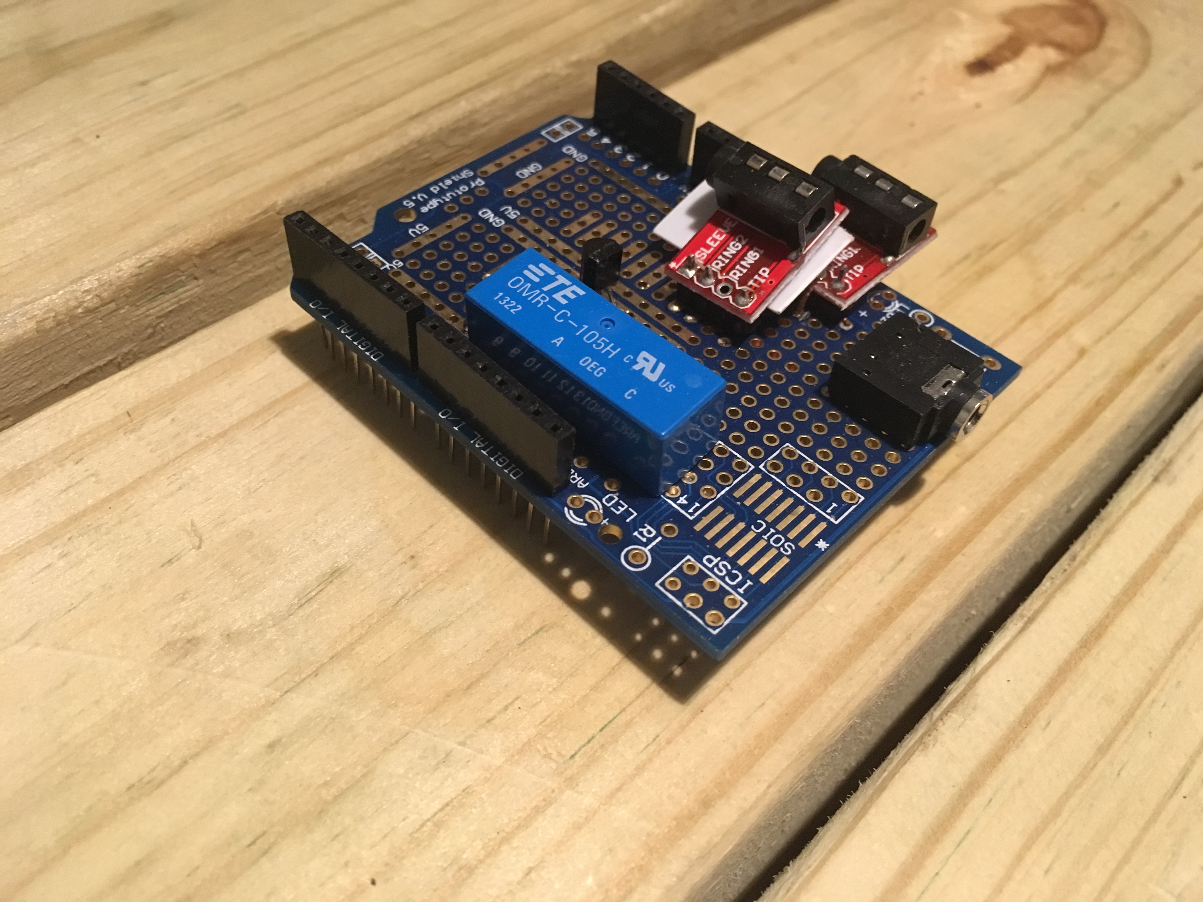
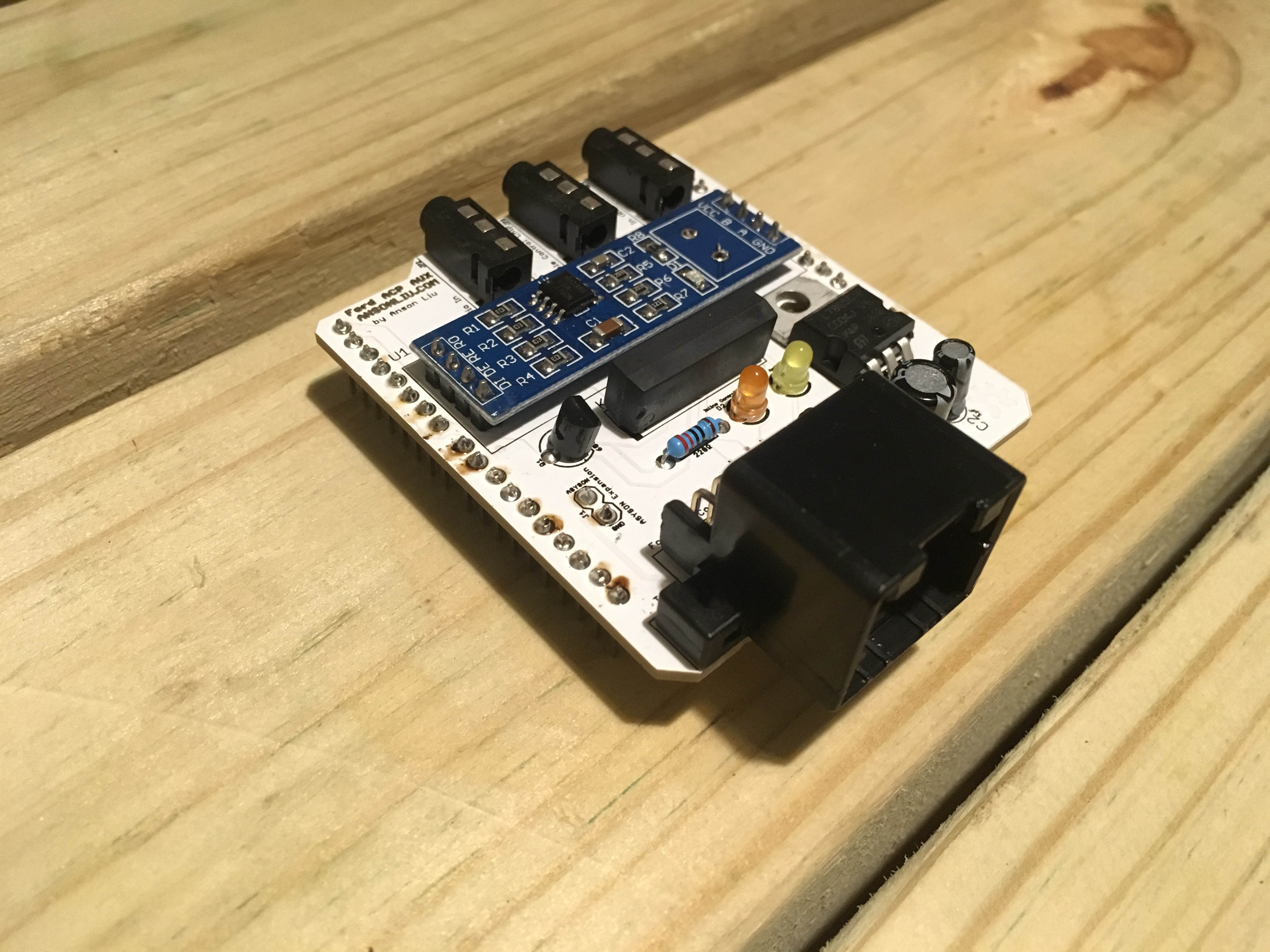
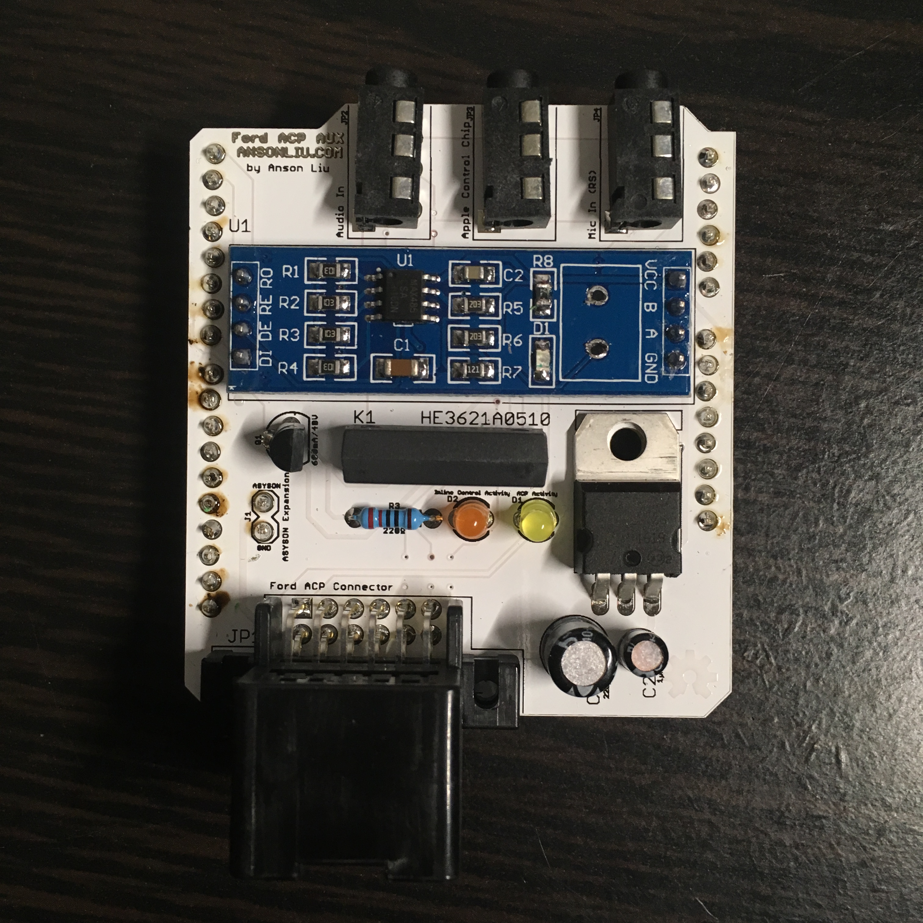
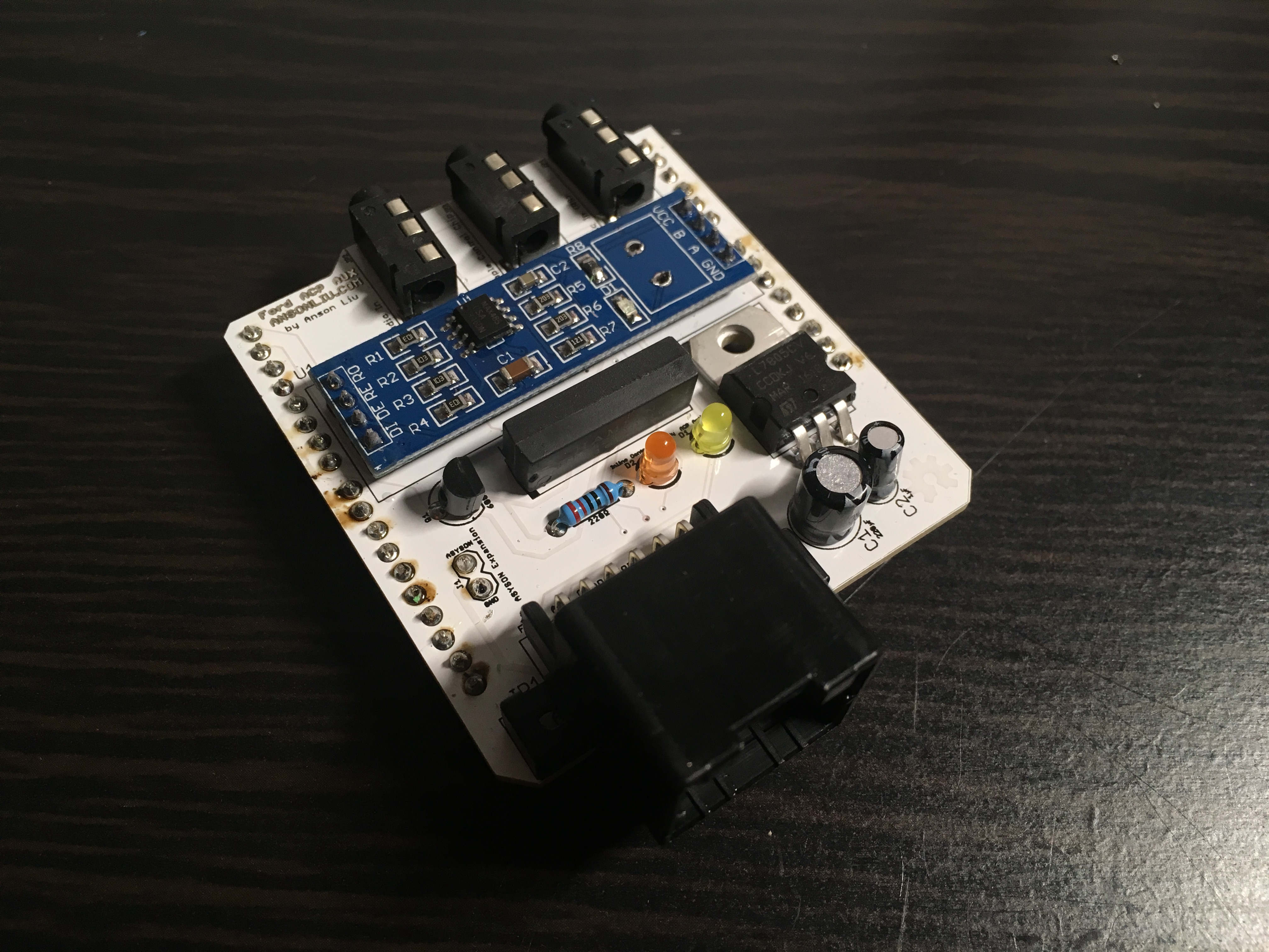
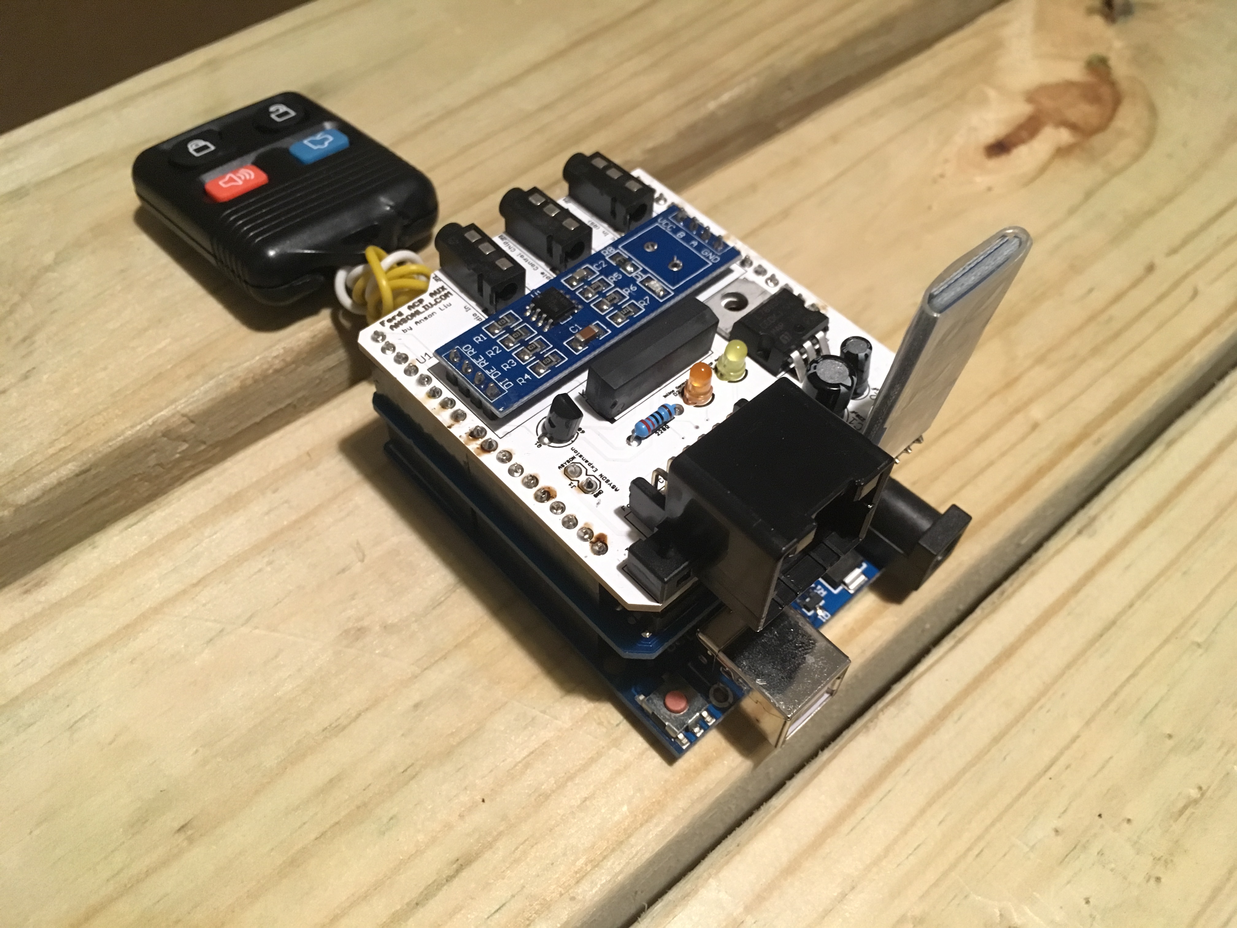
PCB Arrives (2 weeks later)

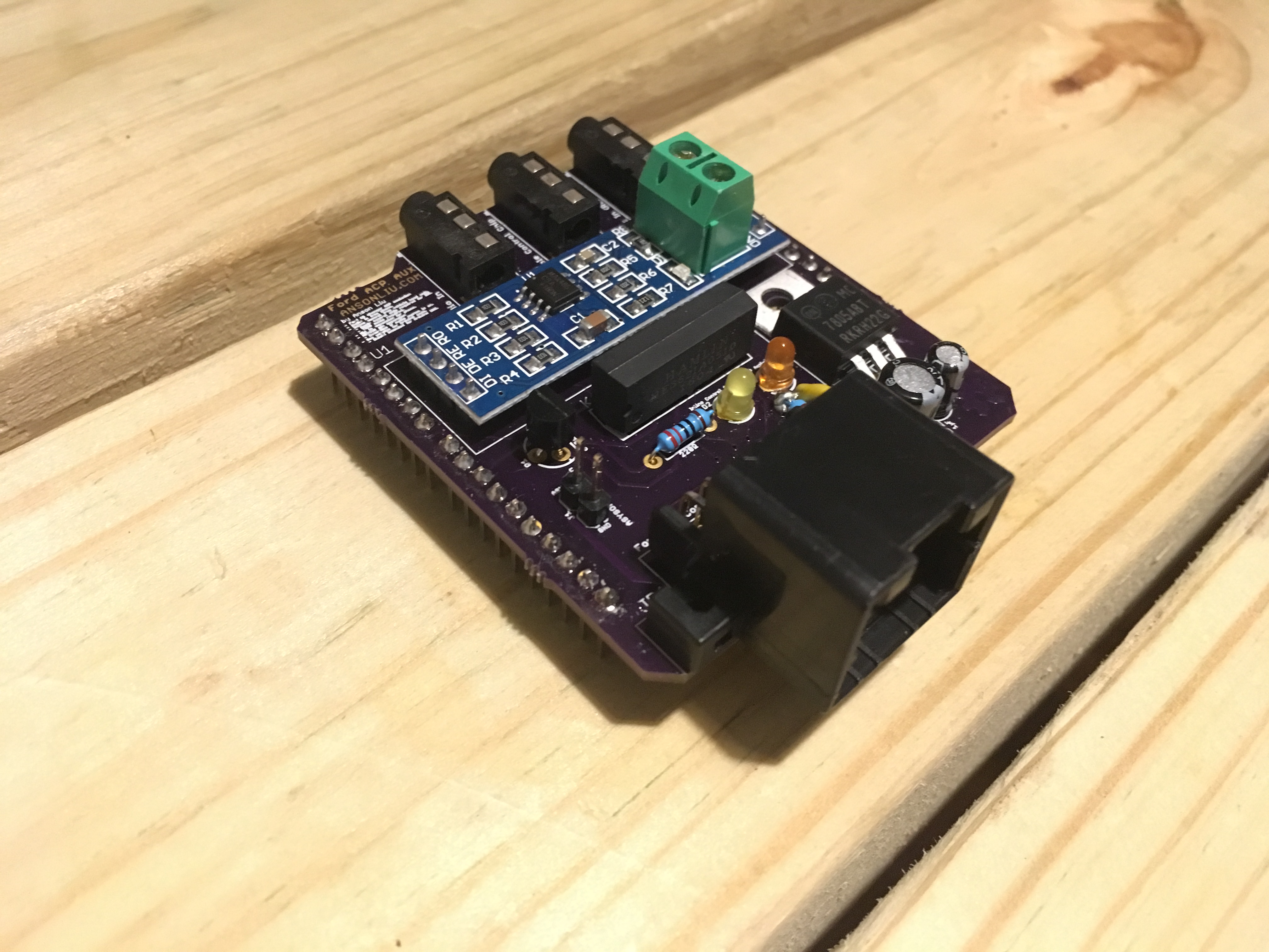
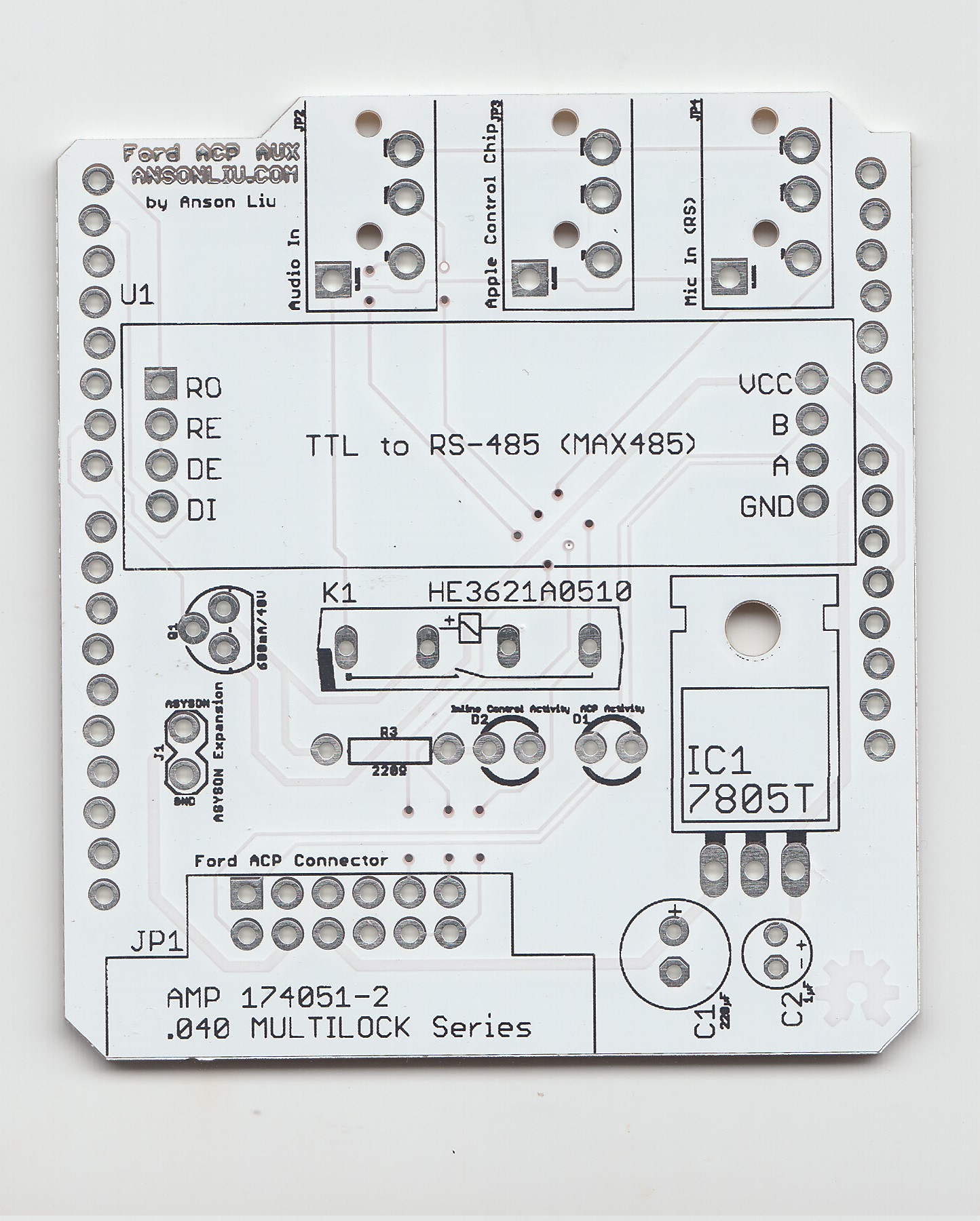
It works and doesn’t disappoint.
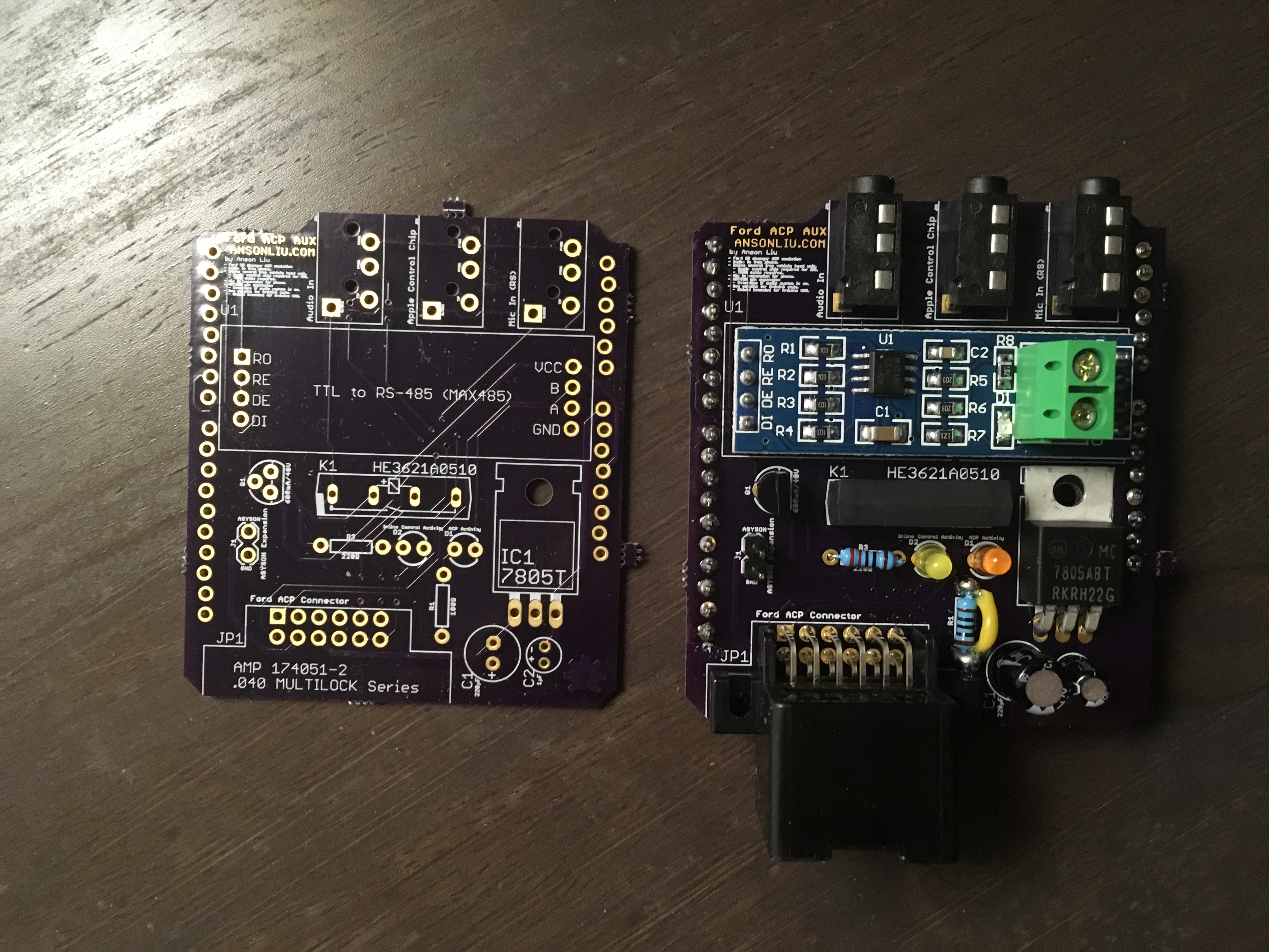
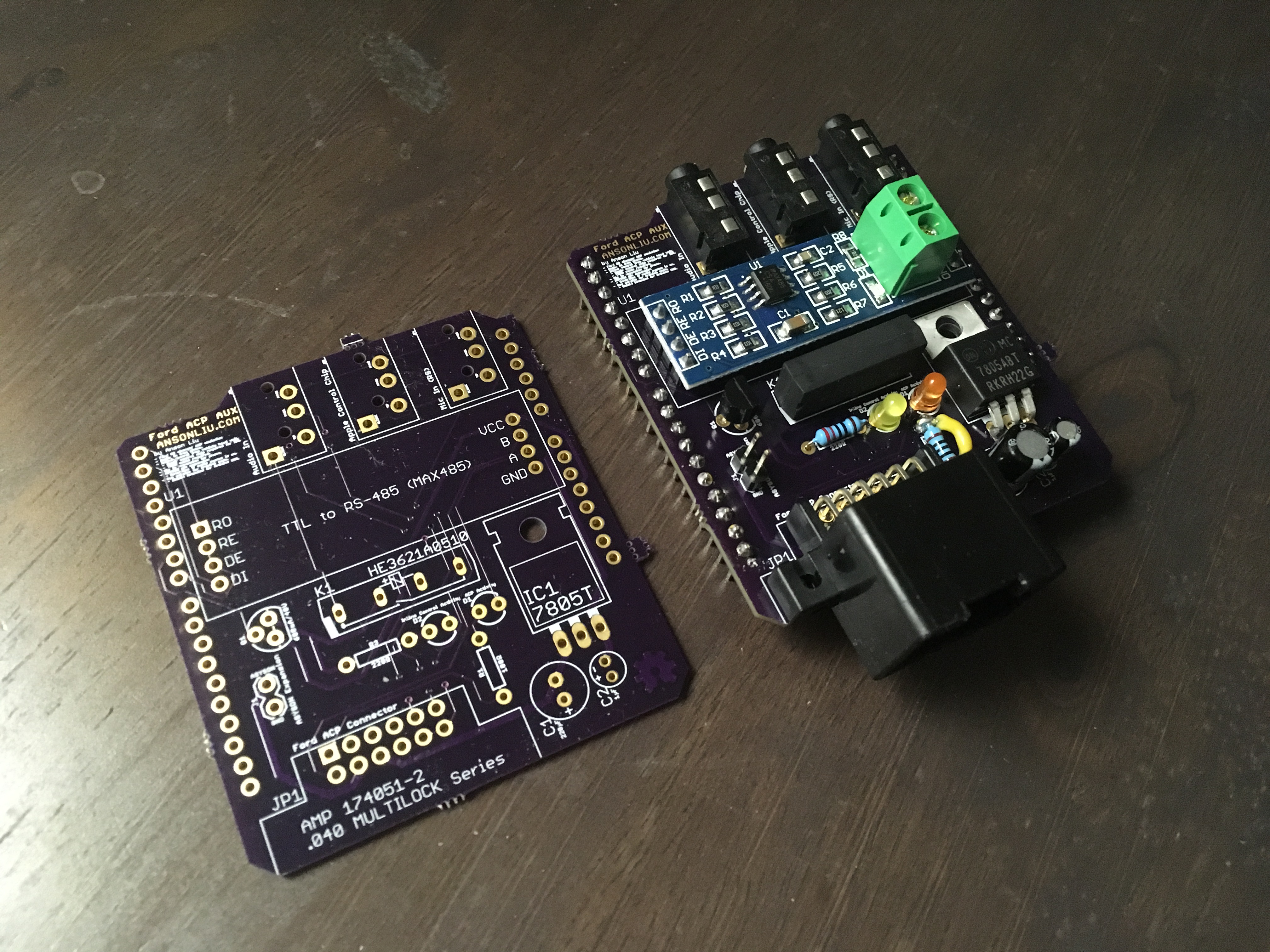
As you may have noticed, I was able to fit both CD changer emulation and playback control functionality on a single Arduino UNO size shield.
| Progress | Goals |
|---|---|
| ✔ | AUX audio in |
| ✔ | Standalone from CD changer |
| ✔ | Reliable connection |
| ✔ | Head unit controlled Next/Previous and Fast Forward/Rewind functionality |
| ✔ | Aesthetics |
I made the wiring mistake of placing the ACP activity indicator LED in series instead of parallel (across ACP A and ACP B lines). The LED in series dropped the voltage below the TTL to RS485 module “high” logic level. A quick fix was to bypass the resistor and indicator LED with a wire and solder bridge. I fixed this mistake in a second PCB order with Seeed Studio Fusion PCB. At the time of writing, Seeed Studio gives $5 coupon to first time customers with a Fusion PCB order in their cart for a few hours.
- Place Fusion PCB order in your cart.
- Do not proceed immediately to checkout.
- Wait a day for the coupon to appear on your account.
- Proceed to checkout and apply coupon within 2 days.
Interpreting ACP Energy Data
The Ford CAN-ACP module converts the Ford 11 bit CAN bus messages to ACP message format. Presumably, this is the energy and fuel efficiency information that is displayed to the user through the navigation head unit. Energy information is represented as arrows pointing to and from the internal combustion engine (ICE), motor, wheels, and battery.
The 9 byte ACP message for CD Changer format is broken down by byte as follows. For more information on the ACP message for CD Changer, please see the document in the repository at Resources/Ford ACP.doc.
| 0 | 1 | 2 | 3 | 4 | 5 | 6 | 7 |
| Priority | Address 1 | Address 2 | Command Control Byte | Data | Data | Data | Data |
Captured ACP energy flow messages appear to be differently sized; 11 bytes in length versus 9 bytes. I love interpretting 11 dimensional data.
I initially captured the ACP messages by writing to an SD card using the Arduino SD library, importing the data as CSV, and creating a scatter plot. The problem with this approach was that I had to mentally recall the recorded drive to find patterns between driving events and the collected data. In the repository, ACP SD datalogging code is located in Sketch/Ford_SD_datalogger.
I was able to figure out the byte at the 7th index indicated the engine was On/Off/Car Off. Not much more was deduced from a non-realtime graph. Attaching an accelerometer in an attempt to capture acceleration and braking did not produce consistent results due to road incline, driving conditions, etc.
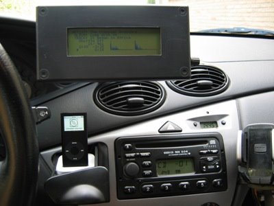
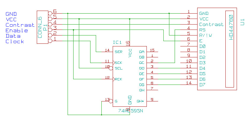
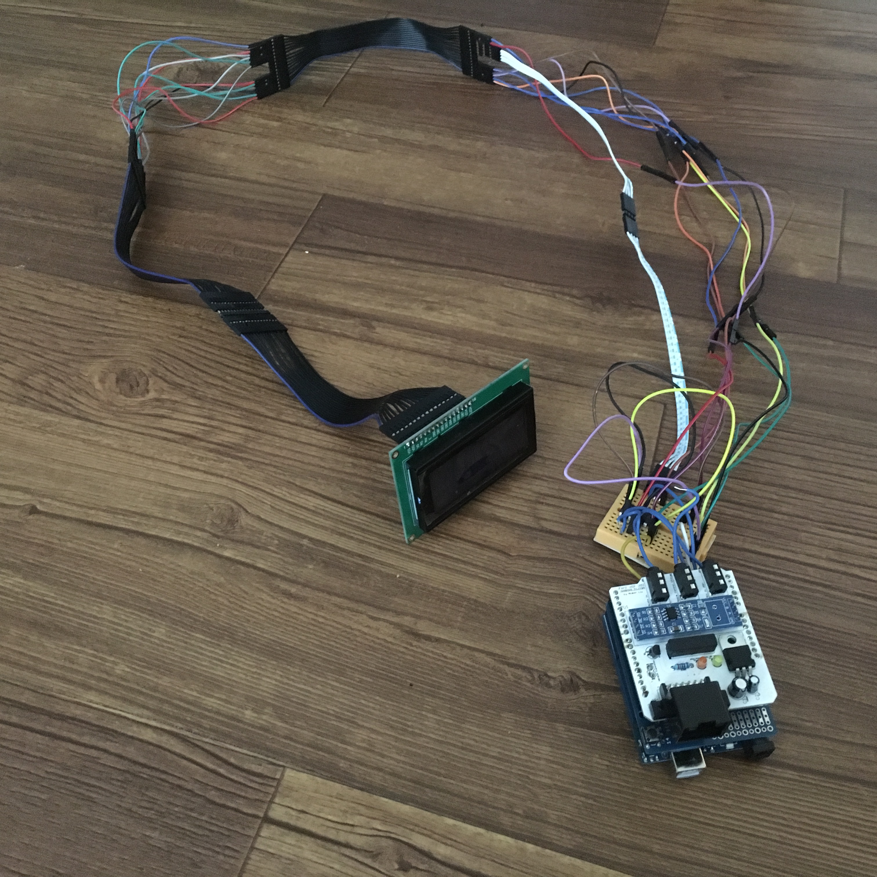
After these unsuccessful ideas and realizing realtime feedback would make decoding data much easier, I hooked up an HD44780 LCD using the 3 wire shift register setup copied below and described in the Arduino New LiquidCrystal library. The reason to use the HD44780 vs segmented LED bars: There was no way I was going to be able to use segmented LED bars to display data without a shift register anyways due to limited ports on the ATMega328.
Based on previously recorded data, the first 4 bytes of energy flow ACP messages remained constant. This leaves 7 bytes of unknown data to interpret. I assume that the remaining 7 bytes of data is “separated” into bytes. Coincidentally, the HD44780 display I used was a 16x4 display of 5x8 cells.
- Each byte of the unknown data would be represented by a display area of 2x4 cells.
- A byte’s maximum decimal value is 255.
- 4 cells vertical length per bypte, each 8 pixels high, gave me a 4×8=32 pixel resolution to display 255 resolution data. See the previous bullet if you are confused about 255.
- The bar graph can be displayed by 1 of 8 block symbols that look like ▁ ▂ ▃ ▄ ▅ ▆ ▇ █
- HD44780 character set only includes the “ “ and █ characters.
Coincidentally (again), the HD44780 supports up to 8 custom characters so we can just create our block symbols in these!
- I initially tried to use rowansimms/arduino-lcd-3pin to drive the display but the library has an issue when creating over five custom characters. 😞
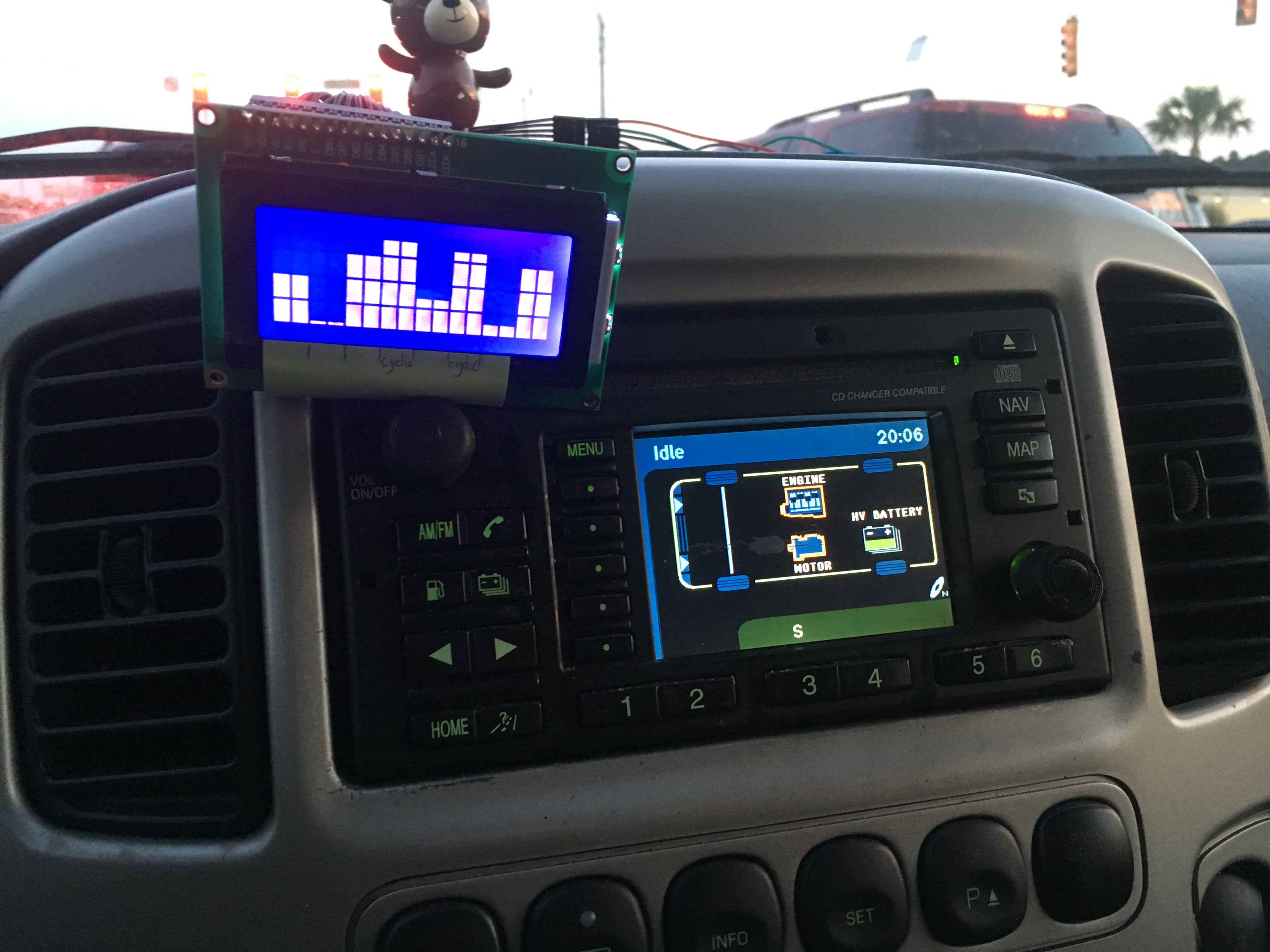
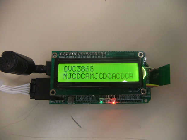
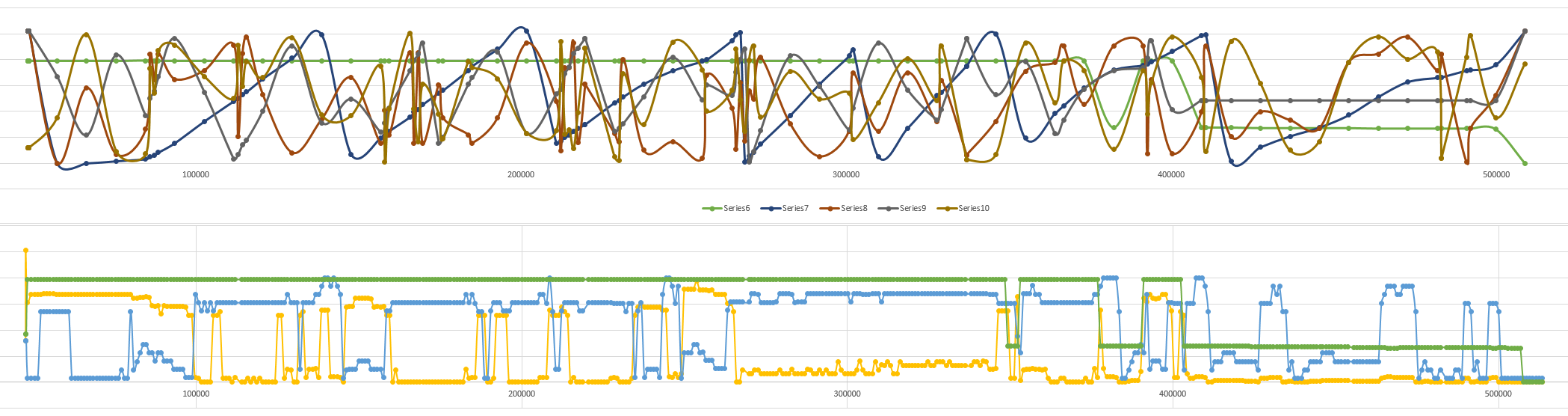
The display works after some fiddling around and realtime ACP data is displayed next to the stock energy display as I drive around. After a few drives with this setup, my guesses for the data are below. For others interested and trying to verify their setup is correct, I have graphed the ACP data in an spreadsheet in the repository at Resources/liu_acp_datalog.xlsx and on Google Sheets.
I could be completely wrong about the data being separated into single bytes. This is an ongoing side project.
| 0 | 1 | 2 | 3 | 4 | 5 | 6 | 7 | 8 | 9 | 10 |
0x71 for my vehicle |
Constant | Constant | Constant | Battery charging? | Electric Motor load | Engine On/Off | ↑ w/ engine + motor use. Resets on max. | ↕ driving / ↓ w/ discharging battery | ↑ w/ engine use. Resets on max. | ↕ driving / ↑ w/ discharging battery |
Memory Management
Updating the LCD with data for extended periods of time (hours) led to points when the unit would become unresponsive and require a power cycle/reset. The 12 position Ford CD Changer connector is “always on” so the microcontroller does not power cycle when the car is started and stopped.
Removing the LCD display updating code resolved the problem. I suspect that the New LiquidCrystal library had a memory leak somewhere within its display update routine. This memory leak would cause the stack/heap to collide with the program code. For normal use I don’t need to graph the ACP data so removing LCD functionality is an acceptable fix; thus I didn’t look into it further.
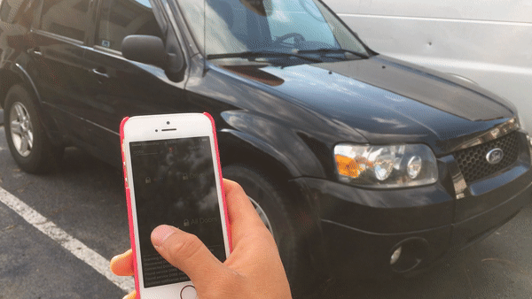
Finishing Up and Demo
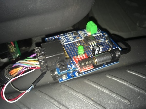
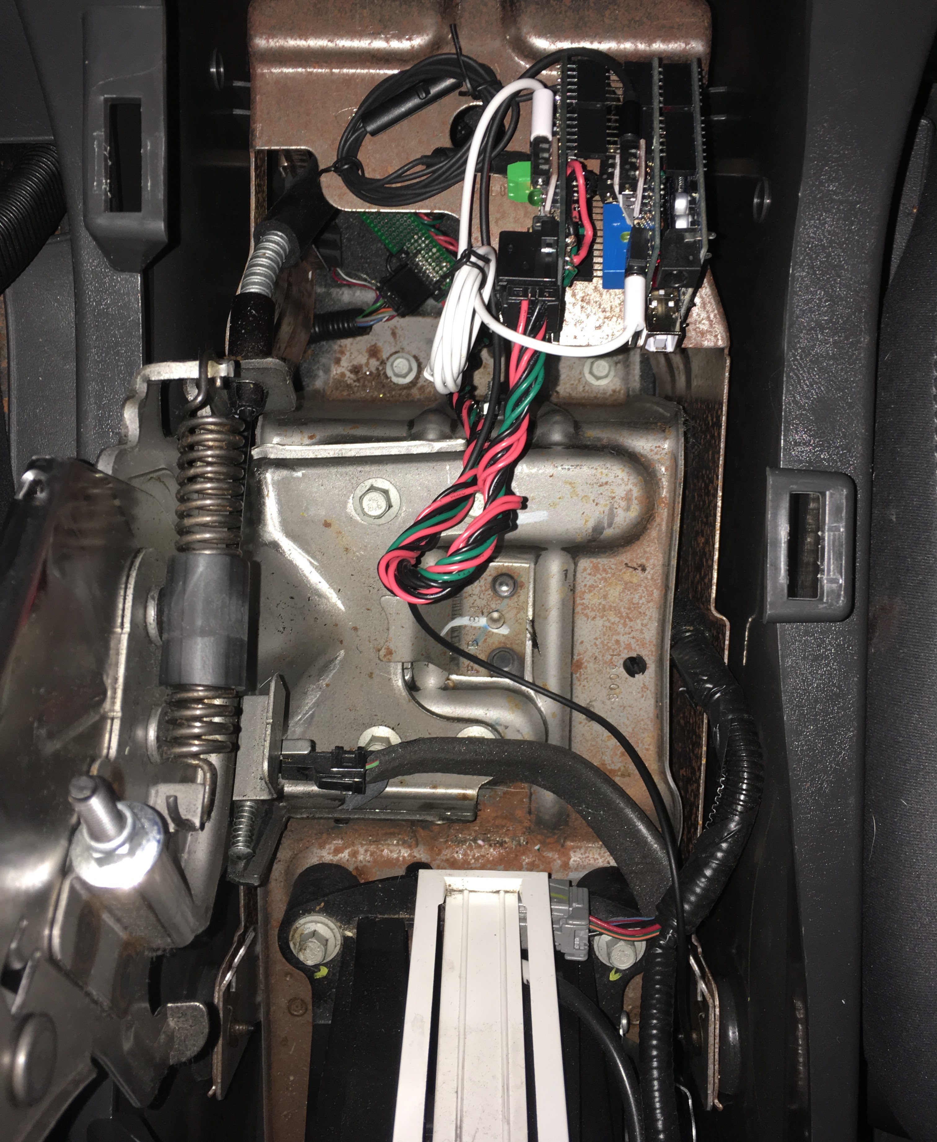
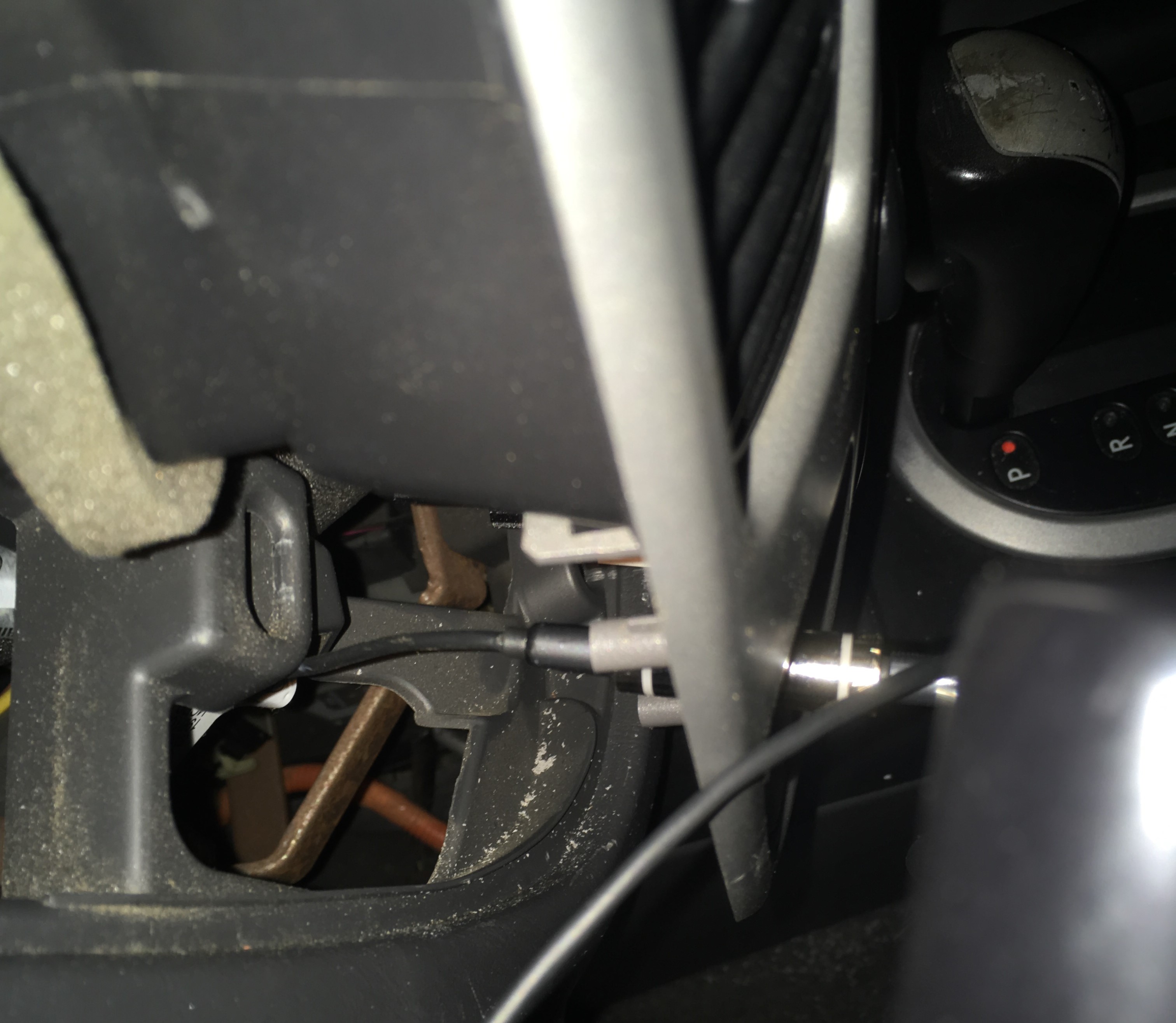
The last thing to do is to plug the finished assembly behind the head unit in a secure position within the Ford Escape. I placed my assembly next to the glovebox.
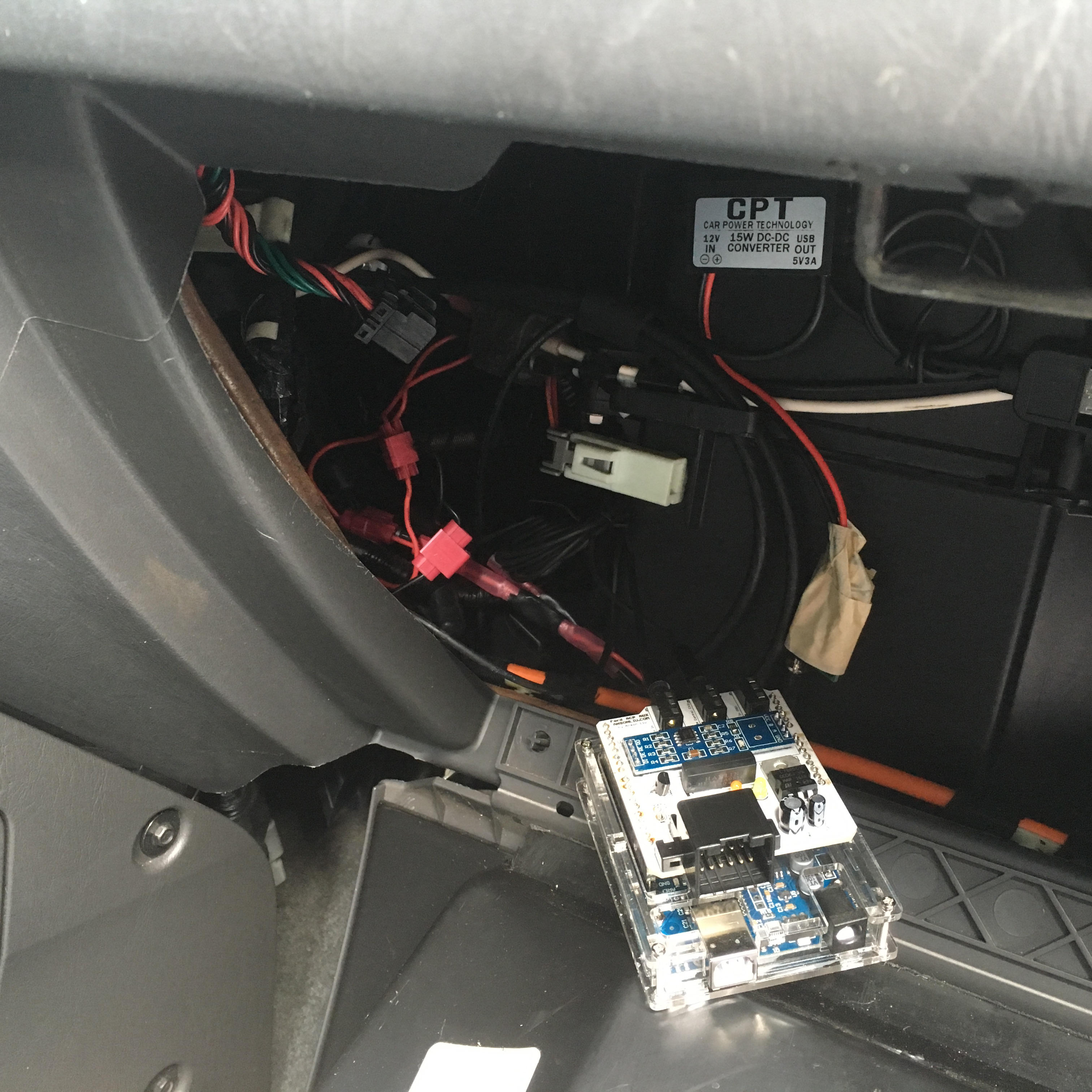

An inexpensive (~$2) acrylic case houses the Arduino UNO itself to prevent the headers on the bottom of the Arduino from contacting the metal vehicle chassis and shorting out.

Anson Liu finally does something.
A year after first splicing the audio cable into the CD connector, I now have a fully integrated AUX audio system (as well as a car data visualizer) that lets me use the original radio head unit controls to control playback on iPhone.
I want this for my Ford XXX but don’t want to order 10 boards from China.
My Seeed Studio order came in a 10 pack so I have a couple boards to spare. Please send me an email.
Compatibility
Measured power consumption of the shield is ~10 mA so the shield should not drain a typical car battery if the vehicle is driven around regularly.
Compatible head units and vehicles (incomplete list)
- 4050RDS
- 4500
- 4600RDS
- 5000RDS
- 5000RDS EON
- 6000CD RDS
- 6000 MP3
- 7000RDS
- 01-07 Ford Escape
- 96-05 Ford Expedition
- Ford Taurus (some)
- Ford Explorer (some)
- Any Ford vehicle with a 12 position CD Changer connector (probably).
Source and Reference Materials
You can get the materials for this project at ansonl /FordACP-AUX. Project includes:
- Source code
- EAGLE schematic and board files
- I recommend printing the PCB with names and values. I have included a Bill of Materials (BOM) in the repository – also accessible online. Cost for parts comes out ~$30 depending on if you intend to hand wire or use a printed board.
- Past contributors’ works in Resources folder.
- I have made an effort to include as many surviving reference materials as I could find.
Credits
Thanks to the work of those below. Their contributions have made this project possible:
- Simon J. Fisher - acpmon
- Andrew Hammond - yampp-3/usb firmware
- sorban - iPod remote control
- Krysztof Pintscher - Yampp → Arduino Mega 2560
- Dale Thomas - Bluetooth Audio support
To be continued?
Check back soon for future posts on wiring up your remote key fob (I don’t want to fry my only car.) for Bluetooth Low Energy (BLE) vehicle security control and more decoding ACP messages for hybrid energy flow information.
